Pneumatic tire

a pneumatic tire and tire body technology, applied in the field of pneumatic tires, can solve the problems of partial wear and blockage of partial wear, and the tendency of partial wear to occur in blocks, so as to reduce the difference (imbalance), improve the partial wear resistance (heel-and-toe resistance), and suppress the collapse of the ribs

Active Publication Date: 2011-05-05
YOKOHAMA RUBBER CO LTD
View PDF22 Cites 6 Cited by
  • Summary
  • Abstract
  • Description
  • Claims
  • Application Information

AI Technical Summary

Benefits of technology

[0007]According to the present invention, as described above, the sipes provided in each block in each shoulder region where partial wear is apt to occur are made different in such a way that the shape of each sipe in the block tread-in side portion differs from the shape of each sipe in the block kick-out side portion. Thereby, the present invention can reduce the difference (imbalance) between the rigidity of the block in the circumferential direction during the braking and the rigidity of the block in the circumferential direction during the driving. For this reason, the present invention can improve the partial-wear resistance (heel-and-toe resistance) in the blocks in each shoulder region.
[0008]Meanwhile, the present invention provides the rib on the tire equatorial plane, and provides the sipes in the rib. Thereby, the present invention can suppress the collapse of the rib during the braking, and thus can secure a wider ground contact area of the rib. For this reason, the present invention can improve the braking performance on ice.

Problems solved by technology

However, the formation of the numeral sipes in the tread surface inevitably entails a problem that partial wear (heel-and-toe wear) is apt to occur in the blocks, and particularly a problem that partial wear is apt to occur in blocks in shoulder regions which are subjected to heavy load during the cornering.

Method used


Image

  • Pneumatic tire
  • Pneumatic tire
  • Pneumatic tire

Examples


examples

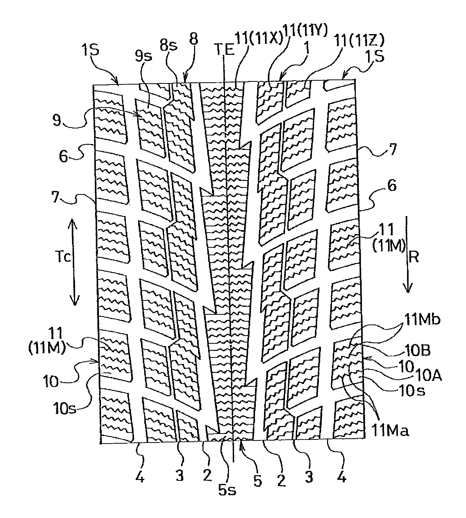
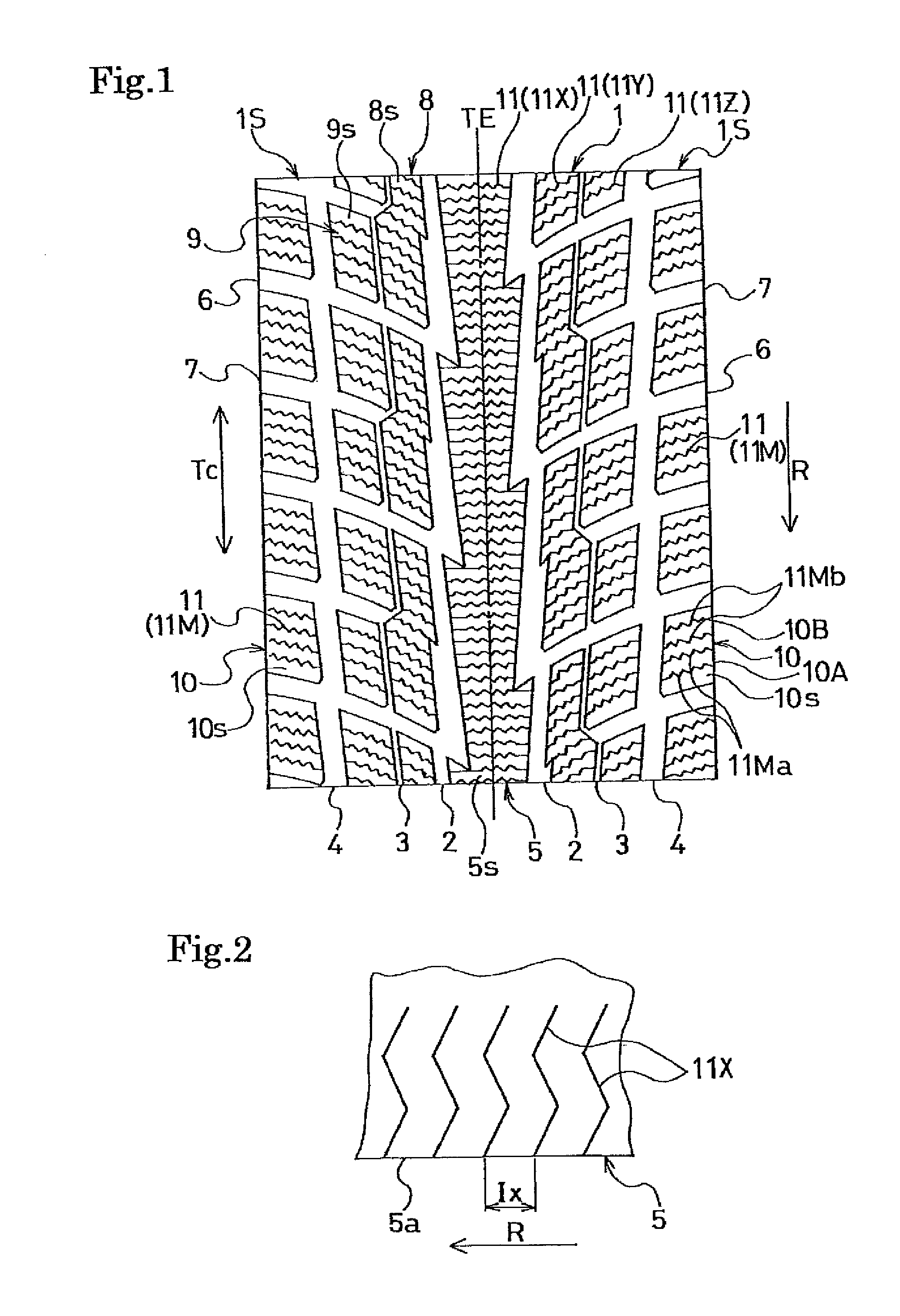
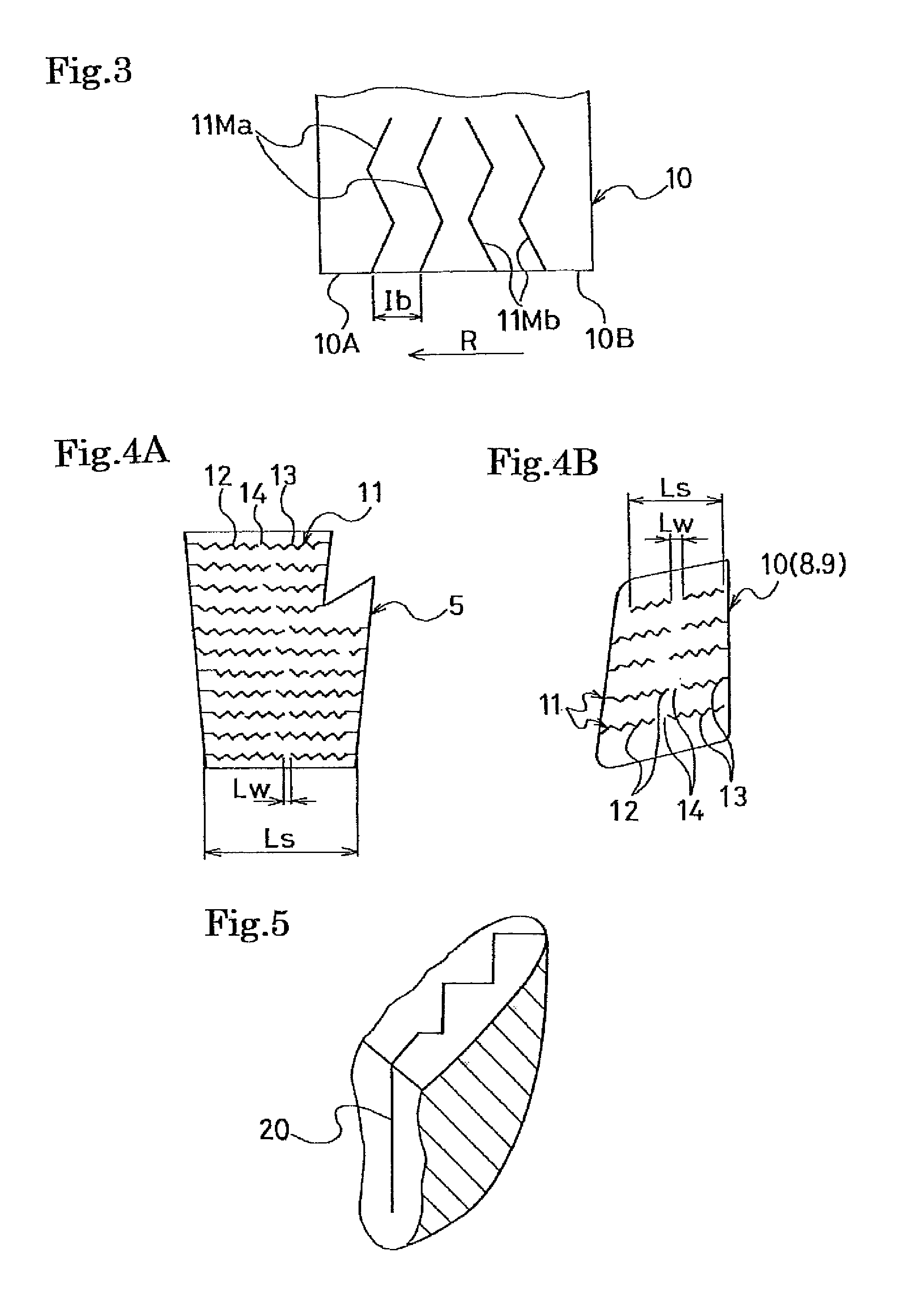
[0035]As experimental tires, tires 1 (Example 1) according to the present invention, tires 2 (Example 2) according to the present invention, tires 3 (Example 3) according to the present invention, reference tires (Reference Example), and comparative tires (Comparative Example) were produced with a common tire size of 225 / 65R17. The tires 1 according to the present invention and the tires 2 according to the present invention had a configuration shown in FIG. 1 in which: the sipes shown in FIG. 2 were provided in the rib on the tire equatorial plane; the sipes shown in FIG. 3 were formed in each block in each shoulder region; and the interval between the sipes in the rib and the interval between the sipes in the block were set as shown in Table 1. The tires 3 according to the present invention had the same configuration as did the tires 2 according to the present invention, except that each sipe in the rib on the tire equatorial plane and each sipe in each block in each shoulder regio...


PUM


Abstract

Provided is a pneumatic tire whose braking performance on ice and partial-wear resistance can be improved. Sipes 11X provided in a rib 5 on a tire equatorial plane TE are formed in such a three-dimensional shape that the amount at which the rib 5 collapses due to an external force is smaller in the tire rotational direction than in a direction opposite to the tire rotational direction. In each block 10 in each shoulder region 1S, sipes 11Ma in a block tread-in side portion 10A are each formed in such a three-dimensional shape that the amount at which the block 10, if entirely provided with the sipes 11Ma, collapses due to an external force will be smaller in the tire rotational direction than in the direction opposite to the tire rotational direction. Sipes 11Mb in a block kick-out side portion 10B are each formed in such a three-dimensional shape that the amount at which the block 10, if entirely provided with the sipes 11Mb, collapses due to an external force will be smaller in the direction opposite to the tire rotational direction than in the tire rotational direction.

Description

TECHNICAL FIELD[0001]The present invention relates to a pneumatic tire used on ice / snow roads, and more specifically to a pneumatic tire whose braking performance on ice and partial-wear resistance are improved.BACKGROUND ART[0002]In conventional pneumatic tires used on ice / snow roads, numerous sipes extending in the tire widthwise direction are arranged in a tread surface in which a block-based tread pattern is formed. The conventional pneumatic tires are designed to secure a better braking performance on ice from an edge effect brought about by the numerous sipes. In addition, the sipes are each formed in a three-dimensional shape. Thereby, the conventional pneumatic tires are designed: to suppress the collapse of the blocks; to thus secure a wider contact area on an ice / snow road; and to exhibit a much higher performance on ice (see Patent Document 1, for instance).[0003]However, the formation of the numeral sipes in the tread surface inevitably entails a problem that partial wea...

Claims


Application Information

Patent Timeline
Patent Type & Authority Applications(United States)
IPC IPC(8): B60C11/12
CPCB60C11/0302B60C11/12B60C11/1218B60C2011/0388B60C2011/1227B60C2011/1254B60C2011/1295B60C2011/1213
Inventor YAMAKAWA, TAKAHIRO
Owner YOKOHAMA RUBBER CO LTD
Why Eureka
Try Eureka