Braking Device for Braking a Lift Car

Active Publication Date: 2011-05-05
THYSSENKRUPP ELEVATOR INNOVATION & OPERATIONS GMBH
View PDF6 Cites 18 Cited by
  • Summary
  • Abstract
  • Description
  • Claims
  • Application Information

AI Technical Summary

Benefits of technology

[0070]By the release mechanism of the braking device, two braking modules can be released symmetrically. That means that both brake shoes simultaneously move away from the rail. Thereby, the lift car even with a not yet completely released brake can start moving without grinding noises. Thereby, even a reduction of the release gap shortly before reaching a hold location is

Problems solved by technology

However, those have the disadvantage that large release gaps can not be realized between friction pads which here are actuated by a coil arrangement and that the weight of the brake is relatively high.
However, such brakes are relatively heavy and require a noisy pneumatic or hydraulic release mechanism which is susceptible to leakage and/or contamination so that they do not allow the use of safe drives for releasing these br

Method used


Image

  • Braking Device for Braking a Lift Car
  • Braking Device for Braking a Lift Car
  • Braking Device for Braking a Lift Car

Examples


first embodiment

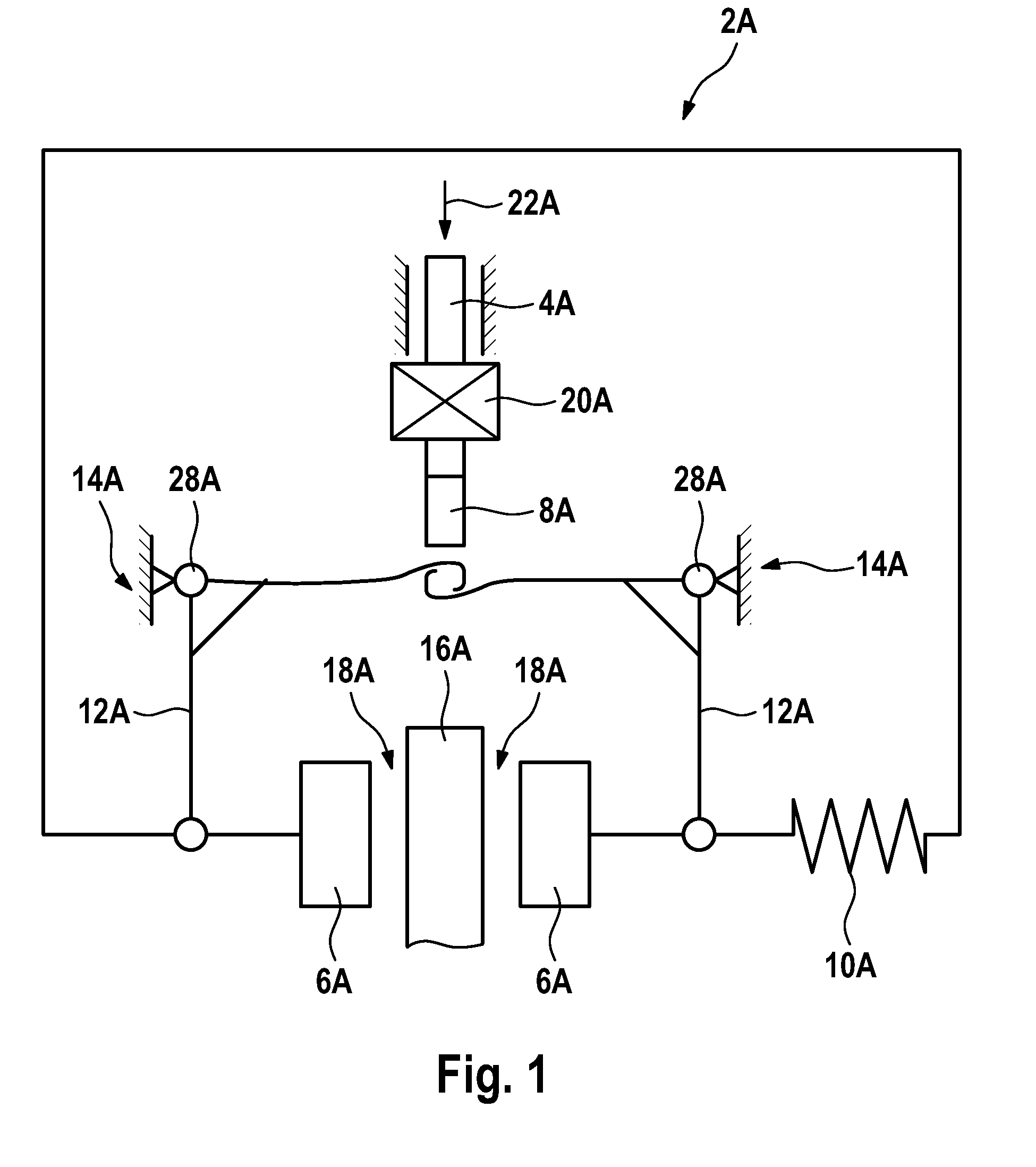
[0091]a braking device 2A for braking a lift car which is schematically illustrated from above in FIG. 1 includes a catch 4A and two braking modules 6A configured as brake shoes which are connected to a common counterpart 8A, wherein this counterpart 8A is in contact with the catch 4A in the operating position shown in FIG. 1. It is provided that the lift car can carry out a movement along a rail 16A as a device. In the context of the present invention, the term “lift car” denotes any kind of “vehicle” for the transport of loads or persons moving relative to a lift shaft.

[0092]In this first operating situation, both braking modules 6A are distanced from the rail 16A with formation of two symmetric release gaps 18A by a spring 10A and two levers 12A which are each supported by fulcrums 28A at a wall structure 14A.

[0093]In this first operating position, it is further provided that an electromagnet 20A pulls the catch 4A upwards (i.e. against gravity). This measure allows to connect th...

fifth embodiment

[0104]FIG. 5 shows a schematic view of a braking device 2E having a catch mechanism which is designed for tensile forces.

[0105]This fifth embodiment of the braking device 2E includes a catch 4E having an arm 24E at the end of which an arc 30E is disposed which has a sphere 32E at one end. The arm 24E of the catch 4E is displacibly and rotatably mounted relative to a wall structure 14E by a fulcrum 28E. At the wall structure 14E also an electromagnet 20E is mounted through which a current is flowing in the operating position shown in FIG. 5 so that it pulls the catch 4E upwards. By another fulcrum 29E, a counterpart 8E of a braking module 6E which in this case has a brake pad 34E is rotatably mounted relative to the wall structure 14E. A spring 10E is compressed between the wall structure 14E and the braking module 6E. The spring 10E is prevented from pressing the braking module 6E to the right by the fact that the catch 4E is connected to the counterpart 8E of the braking module and...

sixth embodiment

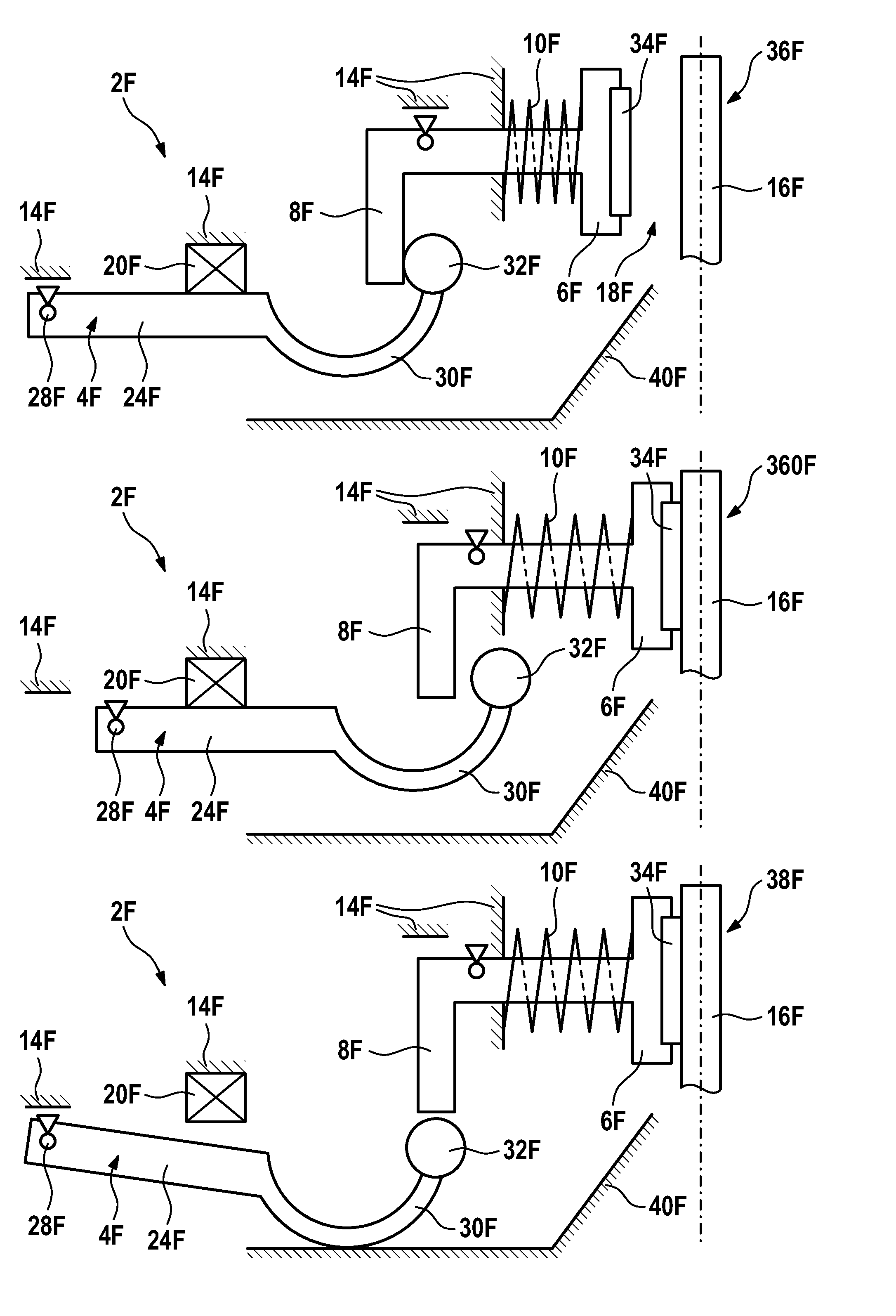
[0107]FIG. 6 shows a braking device 2F in three different operating positions, i.e. a first variant of a first operating position 36F in an upper portion of FIG. 6, a second variant of a first operating position 360F in a middle portion of FIG. 6, and an embodiment of a second operating position 38F in a lower portion of FIG. 6.

[0108]FIG. 6 shows a sixth embodiment of a braking device in three operating positions 36F, 360F, 38F of a catch 4F and resulting operating positions of a braking module 6F. In detail, the braking device 2F comprises a catch 4F having an arm 24F, an arc 30F and a sphere 32F, wall structures 14F and furthermore the braking module 6F having a counterpart 8F and a brake pad 34F. In this context, a spring 10F is tensioned between the braking module 6F and one of the wall structures 14F. Moreover, FIG. 6 shows a stationary device designed as a rail 16F and electromagnets 20F. FIG. 6 also shows a catching aid 40F configured as a path having an inclined plane.

[0109]...


PUM


Abstract

A braking device (2) for braking a lift car which moves relative to a lift shaft, having at least one braking module (6) which is provided in order to interact with a device, and having a catch (4) which can be adjusted between two operating positions (36, 360, 38), wherein the catch (4), in a first operating position (36, 360), is connected to the at least one braking module (6) such that the catch (4) transmits a release force (22) to the at least one braking module (6), and wherein the catch (4), in a second operating position (38), is separated from the at least one braking module (6), and the at least one braking module (6) is therefore in contact with the device.

Description

RELATED APPLICATIONS[0001]This is a continuation of International PCT Application No. PCT / EP2008 / 008647, filed Oct. 13, 2008, claiming the priority benefit of EPC 07 021 915.9, filed Nov. 12, 2007, hereby incorporated by reference.FIELD OF THE INVENTION[0002]The invention relates to a braking device for braking a lift car, a lift facility, and a method for adjusting at least one braking module.BACKGROUND OF THE INVENTION[0003]For braking and catching a lift car of a lift facility, different mechanisms are known which can be realized by suitable braking devices.[0004]For providing strong compression forces, for example, for a brake and for being able to release these forces in the so-called fail-safe mode and thus in a fail-safe or failure-resistant operation, commonly electromagnets are used as described in the document DE 100 49 168 A1, for example. However, those have the disadvantage that large release gaps can not be realized between friction pads which here are actuated by a co...

Claims


Application Information

Patent Timeline
IPC IPC(8): B66B5/18
CPCB66B5/18
Inventor DUDDE, FRANKFEDERLE, PHILLIP
Owner THYSSENKRUPP ELEVATOR INNOVATION & OPERATIONS GMBH
Why Eureka
Try Eureka