
Wheel chock having a roller assist

Inactive Publication Date: 2011-05-05
BIRD STEVE K +1
View PDF19 Cites 9 Cited by
  • Summary
  • Abstract
  • Description
  • Claims
  • Application Information

AI Technical Summary

Benefits of technology

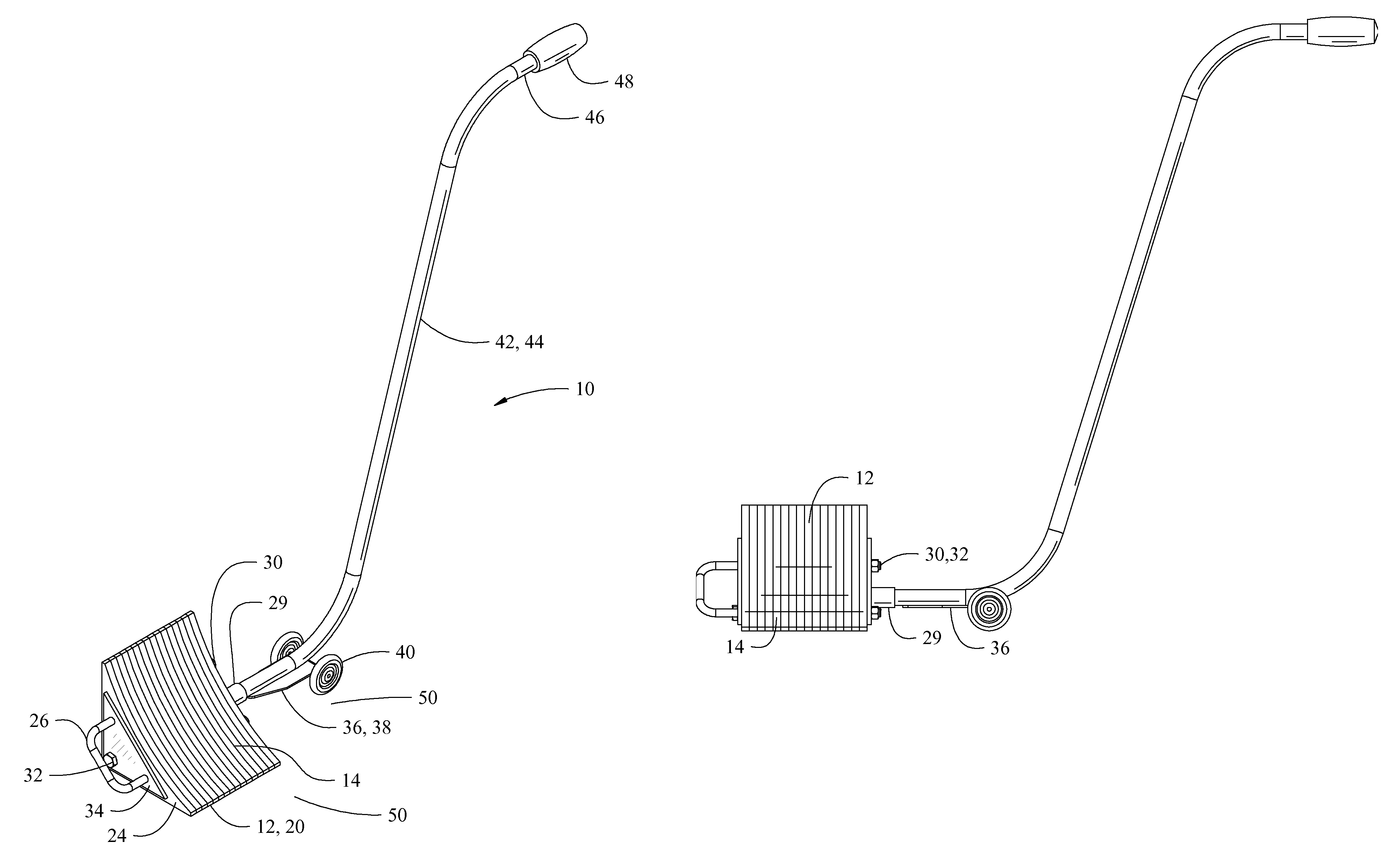
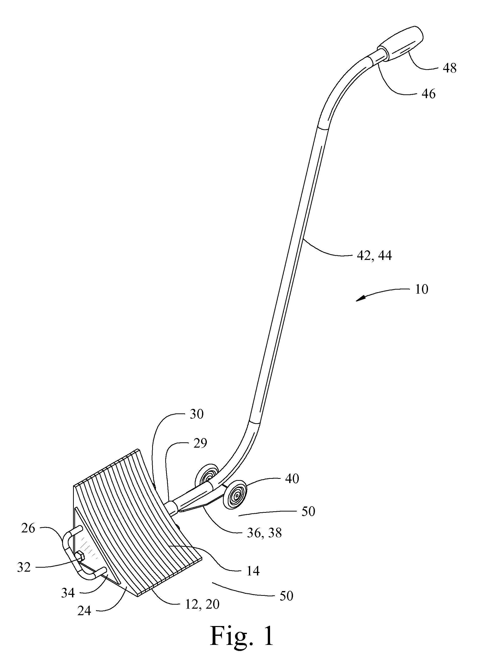
[0009]In its preferred form, the art of the present invention represents a chock in the form of a generally wedge shaped structure with a wheel contacting surface, a bottom surface, a front surface, a proximal surface, and a distal surface. The preferred embodiment utilizes a wedge shape of approximately eight inches in width and height which is formed from a laminated rubber or rubber like material. The rubber or rubber like material maximizes the coefficient of static friction with the pavement upon which the chock rests. (i.e. an approximate value of 1.0 on concrete whereas the lightweight aluminum extrusion of Metz has an approximate value less than 0.6)
[0013]For the preferred embodiment, the distal surface of the chock has a chain or cable attachment assembly in the form of an eyelet or “U” shaped extension extending therefrom. This allows the apparatus to be secured to a building, structure, or post in order to prevent theft and unauthorized use.
[0014]Operation of the apparatus is simple and intuitive. The user first simply disconnects the apparatus from any building, structure, or post with which it is attached. The user then presses downward (towards the pavement) upon the proximal grip portion and rolls the apparatus to a desired location such as under or behind a vehicle wheel. After use, the user simply repeats the aforesaid procedure and rolls the apparatus to a desired location. The roller assembly allows for easy and convenient placement of the chock and construction of the chock from a heavy and durable material.

Problems solved by technology

Unfortunately, wheel chocks having the required durability are often so heavy that they cannot be easily placed under or mated with the wheels of a vehicle by a single user without undue stresses placed upon the user.
Unfortunately, a lightweight chock is generally not as sturdy or as likely to inhibit the vehicle from moving.

Method used


Image

  • Wheel chock having a roller assist
  • Wheel chock having a roller assist
  • Wheel chock having a roller assist

Examples


Embodiment Construction

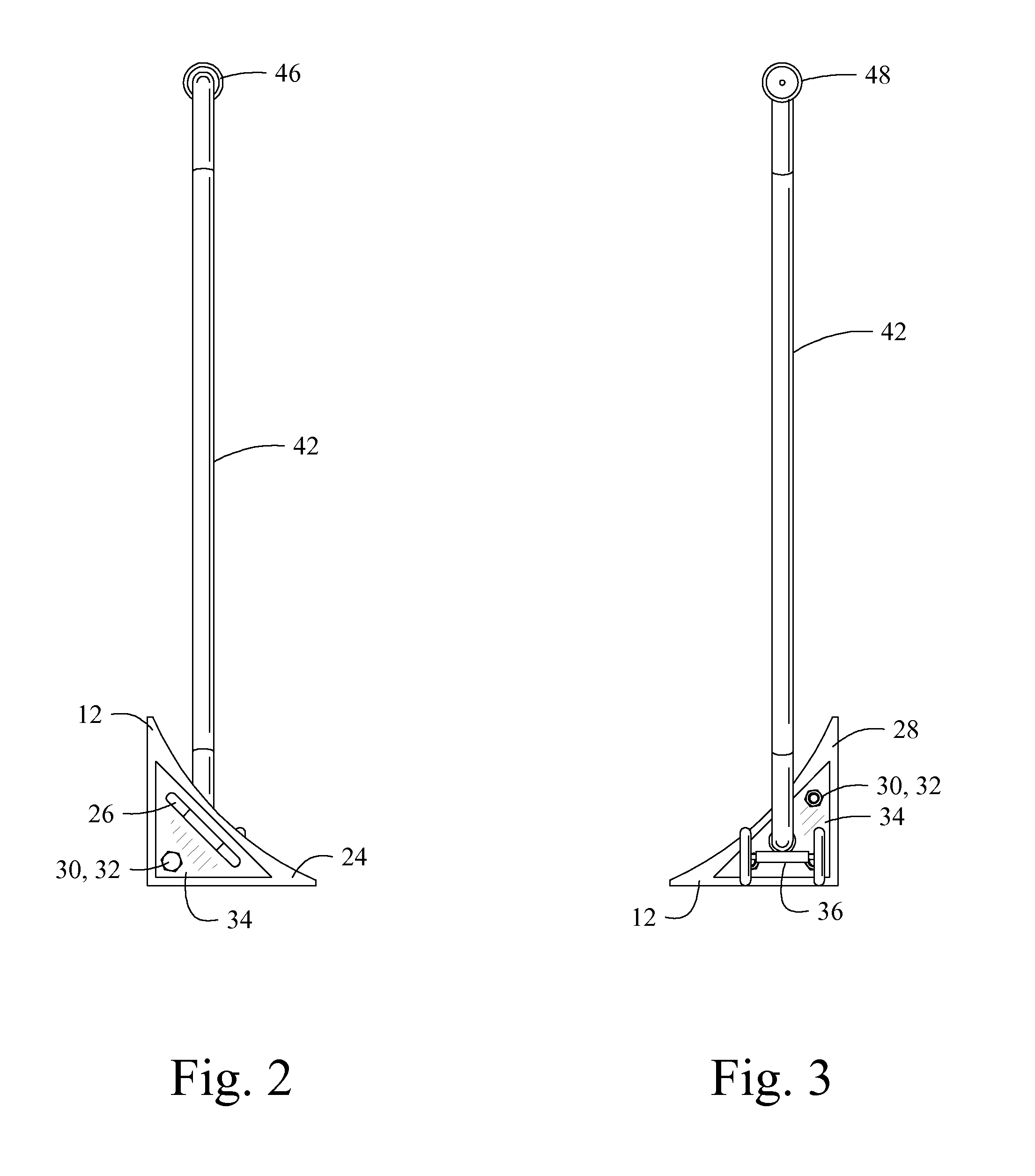
[0024]Referring now to the drawings, there is shown in the Figures a preferred embodiment of a wheel chock having a roller assist 10. In its preferred form, the present art apparatus 10 comprises a chock 12, a handle assembly 42, and a roller assembly 36 upon which the entire apparatus 10 may be rolled into position.

[0025]In its preferred form, the art of the present invention represents a chock 12 in the form of a generally wedge shaped structure with a wheel contacting surface 14, a bottom surface 16, a front surface 18, a proximal surface 28, and a distal surface 24. Preferably said contacting surface 14 is contoured or shaped, i.e. a arcuate surface, to mate or touch with a vehicle wheel. For the preferred embodiment the chock 12 is formed from a laminated rubber or rubber like belting material 20 having a plurality of layers (laminations) with one or more fasteners 30 extending through the laminations 20. The fasteners 30 are capable of compressing the laminations 20 together a...


PUM


Abstract

A wheel chock having a roller assist comprised of a chock, a handle assembly, and a roller assembly. The wheel chock is controlled and lifted by the handle assembly pivoting on the roller assembly. The roller assembly allows rolling of the chock by a user without the necessity of actually lifting the chock. The preferred embodiment utilizes a chock of a heavy and structurally strong rubber or rubber like laminated belting material. The belting material provides an assured grip with the underlying pavement and also forms a structure which is substantially indestructible by a vehicle or a truck.

Description

BACKGROUND OF THE INVENTION[0001]The art of the present invention relates to wheel chocks in general and more particularly to a wheel chock and method of use having one or more rollers or dollies and an extending handle or arm which allows a user to easily place the chock behind a wheel without the usual bending, stooping, or kneeling required with prior art chock devices. The art of the present invention is especially useful for persons having disabilities or other ailments which limit their ability to bend, stoop, or kneel.[0002]Wheel chocks (i.e. chocks) are generally wedge shaped structures of a sturdy (and generally heavy) material which are typically placed behind one or more vehicle's wheels in order to prevent accidental vehicle movement and promote safety. The bottom surface often has a coating or is manufactured from a material that enhances the grip with the pavement, ground, or floor beneath the chock. The coefficient of static friction of the bottom surface dictates tha...

Claims


Application Information

Patent Timeline
IPC IPC(8): B60T3/00B62B1/02
CPCB62B1/02B60T3/00
Inventor BIRD, STEVE K.BALES, ROBERT
Owner BIRD STEVE K
Learn More