Multi-Channel Electrospray Emitter
- Summary
- Abstract
- Description
- Claims
- Application Information
AI Technical Summary
Benefits of technology
Problems solved by technology
Method used
Image
Examples
working examples
Example 1
Sample Preparation and Reagents
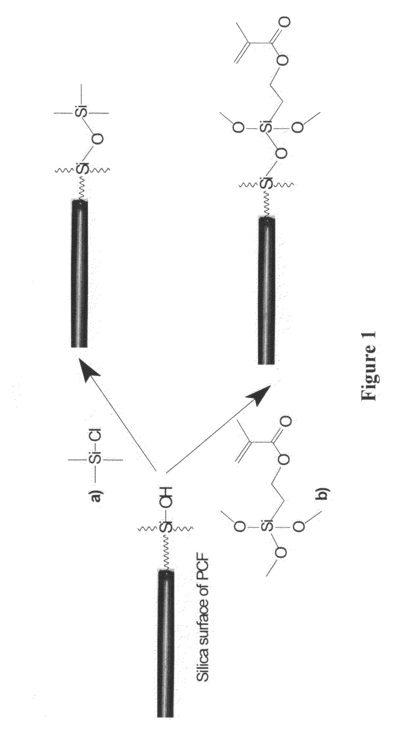
[0080]Methanol, toluene, glacial acetic acid and acetonitrile (HPLC grade) were purchased from Fisher Scientific (Ottawa, ON Canada) and used without further purification. Formic acid (analytical reagent, 98%) was purchased from BDH Chemicals, (Toronto, ON Canada). Leucine enkephalin (synthetic acetate salt), [3-(methacryloyloxy)propyl]trimethoxysilane (γ-MAPS) and chlorotrimethylsilane (98%) (CTMS) were from Aldrich (Oakville, ON Canada). Deionized water was obtained from a Milli-Q system (Millipore, Bedford, Mass., USA) and was 18 MΩcm or better in resistance.
[0081]Two groups of PCFs were used. For the first group, F-SM16 and F-SM20, obtained from Newport Corporation (Irvine, Calif., USA), were used. The F-SM16 PCF had 30 channels, and each channel had an internal diameter of 4 to 5 μm. The F-SM20 PCF had 168 channels, and each channel had an internal diameter of 4 to 5 μm. For the second group, PCFs having 30, 54, 84, and 168 channels were ...
example 2
[0103]In MSF emitters prepared with a flat tip face, the spray from individual nozzles may coalesce, detracting from the multiple spray effects. This effect may be reduced by functionalizing the spray surface with a hydrophobic monolayer coating, such as chlorotrimethylsilane (CTMS). Whereas hydrophilic solvents are less likely to coalesce, the problem does persist. In this example each nozzle was raised above the surface of the MSF face, to promote individual spray from each nozzle. FIG. 11a shows a MSF emitter with a flat tip face, and FIG. 11b shows a MSF emitter with raised nozzles.
[0104]To raise the nozzles of the emitter as shown in FIG. 11b, an initial investigation was carried out using wet etching with ammonium bifluoride. A 54-channel MSF was etched for three hours while flowing water through the channels. However, too much of the tip face was etched away, such that the nozzle structure was not maintained, and Taylor cone segregation was unlikely even at lower etching time...
example 3
[0139]In certain applications it is desirable to have a multi-channel electrospray emitter that can produce multiple electrosprays (e.g., a distinct Taylor cone produced by each nozzle). However, as noted above, in MSF emitters prepared with a flat tip face, the spray from individual nozzles may coalesce, detracting from the multiple electrospray (ME) spray effect. In this example multiple electrosprays were produced using emitters with smaller numbers of nozzles.
[0140]Emitters were prepared from a two channel pulled glass MSF and one, three, and nine channel polycarbonate MSFs. The arrangements of the channels / nozzles in the three and nine channel MSFs are shown in FIGS. 15a and 15b.
[0141]Tests were run to measure the spray stability and current of two channel emitters prepared from glass MSF, and one, three, and nine channel emitters prepared from polycarbonate MSF. The emitter was placed 2-3 mm from a gold coated wire mesh. A custom pump (Upchurch Scientific, Oak Harbor, Washing...
PUM
 Abstract
Description
Claims
Application Information
 - R&D
- Intellectual Property
- Life Sciences
- Materials
- Tech Scout
- Unparalleled Data Quality
- Higher Quality Content
- 60% Fewer Hallucinations
Browse by: Latest US Patents, China's latest patents, Technical Efficacy Thesaurus, Application Domain, Technology Topic, Popular Technical Reports.
© 2025 PatSnap. All rights reserved.Legal|Privacy policy|Modern Slavery Act Transparency Statement|Sitemap|About US| Contact US: help@patsnap.com


