Eureka AIR delivers breakthrough ideas for toughest innovation challenges, trusted by R&D personnel around the world.

Spring Generator

Inactive Publication Date: 2011-05-05
WILLIAMS JAMES
View PDF14 Cites 10 Cited by
  • Summary
  • Abstract
  • Description
  • Claims
  • Application Information

AI Technical Summary

Benefits of technology

[0010]Yet another object of this invention is to provide a spring operated generator, as aforesaid, that is easy to operate and economical to manufacture.

Problems solved by technology

Businesses require an ever larger amount of energy.
And, of course, many smaller devices require smaller amounts of electrical power.
Although assumably effective for their intended purposes, the existing systems tend to be large, expensive, inefficient, or require use of large amounts of natural resources such as coal which has a negative environmental impact.

Method used


Image

  • Spring Generator
  • Spring Generator
  • Spring Generator

Examples


Embodiment Construction

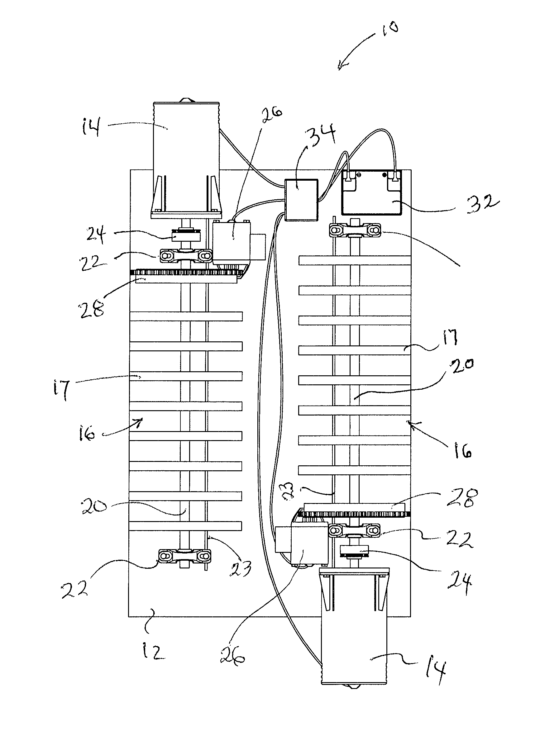
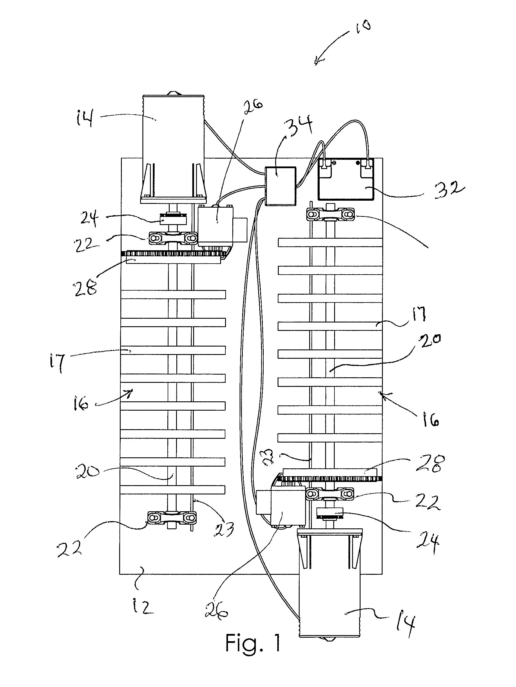
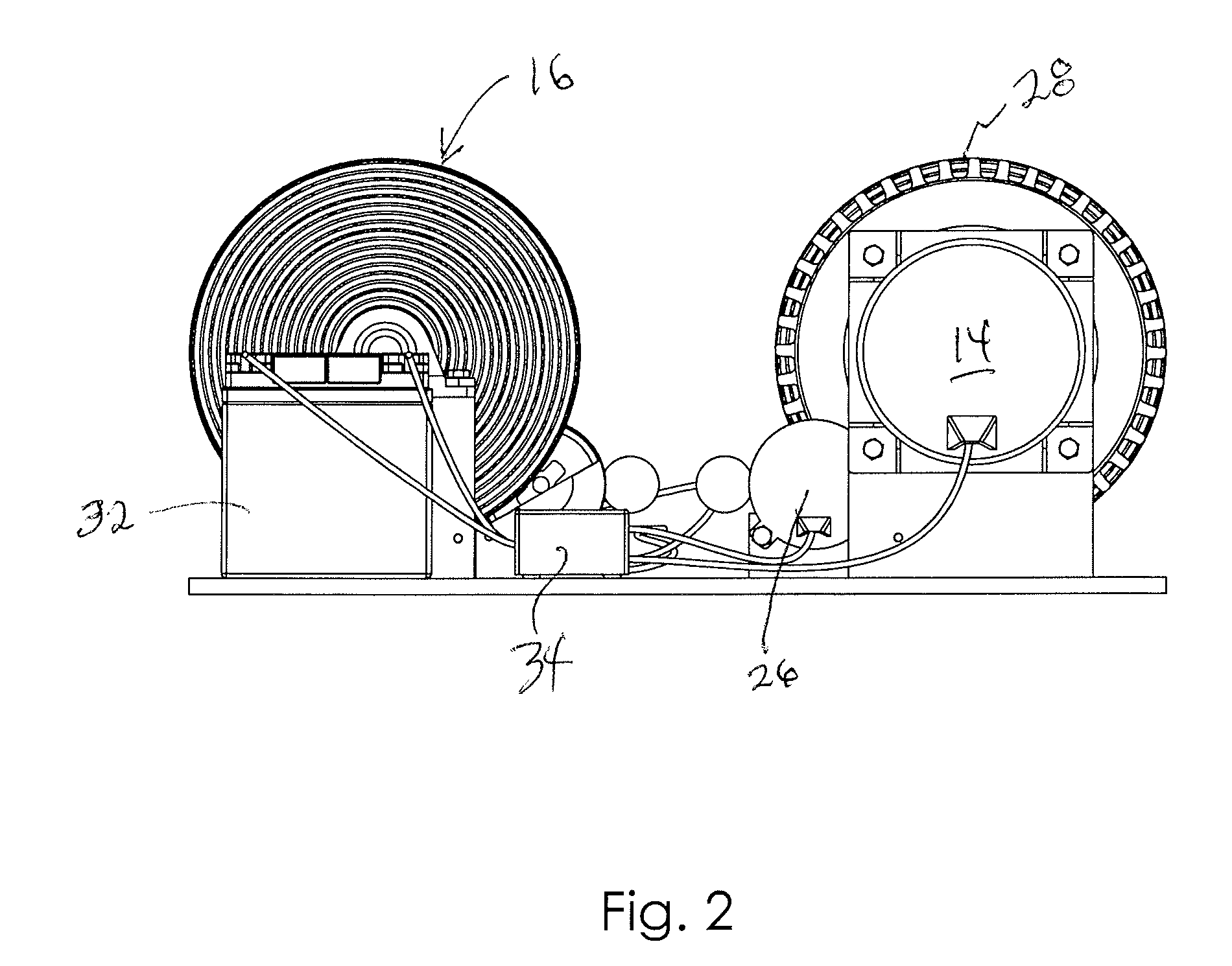
[0018]A spring operated generator 10 according to a preferred embodiment of the present invention will now be described in detail with reference to FIG. 1 to 5 of the accompanying drawings. The spring operated generator 10 may be a singular device or may include two completely individual devices mounted in close proximity to one another and electrically linked by a common controller 34, such that one operates to generate electricity at all times, as will be described more fully below. A pair of spring operated generators 10 is preferred and may be referred to in this application as a singular unit with the same reference numerals being used for each. In some instances, however, the pair of spring operated generators may be referred to separately (using the reference term “respective” or “respectively”) so as to clearly explain the relationship of a pair of generators being operational relative to one another.

[0019]The spring operated generator 10 includes a base plate 12 to which al...


PUM


Abstract

A spring operated generator includes a pair of torsion spring banks and a pair of elongate shafts extending through respective spring banks and operatively connected to respective generators. A starter motor is connected to each respective spring bank for initially winding each spring bank. When actuated, the primed spring bank is allowed to unwind. A clutch coupled to the elongate shaft is configured to engage a respective generator, transferring energy from shaft rotation to the generator which produces electricity. As one spring bank unwinds, the other spring bank is wound in like manner as the first. When the initial spring bank is unwound and the other spring bank is sufficiently wound, the cycle is repeated, thereby causing the other generator to produce electricity.

Description

CROSS-REFERENCE TO RELATED APPLICATIONS[0001]The present invention claims the benefit of U.S. Provisional Patent Application, Ser. No. 61 / 257,577, filed on Nov. 3, 2009 titled SPRING GENERATOR.BACKGROUND OF THE INVENTION[0002]This invention relates generally to a spring operated generator and, more particularly, to a spring arrangement that operates a generator to generate electricity as each spring unwinds. The spring may again be wound with a starter motor using a portion of electricity generated and stored as a result of the spring unwinding. Preferably, two spring generators are utilized together so that one spring generator is being wound while the other is generating electricity.[0003]The production of energy and, particularly, electricity is very important in our world today due to all the modern conveniences that people consider mandatory or commonplace. Houses are growing larger and require more electricity for operating lights, appliances, and the like. Businesses require ...

Claims


Application Information

Patent Timeline
IPC IPC(8): F02B63/04F03G7/10
CPCF03G7/10
Inventor WILLIAMS, JAMES
Owner WILLIAMS JAMES
Why Eureka
Eureka Blog
Learn More