Energy harvesting device

a technology of energy harvesting device and energy storage, which is applied in the direction of piezoelectric/electrostrictive/magnetostrictive devices, piezoelectric/electrostrictive/magnetostriction machines, electrical equipment, etc., can solve problems such as elastic deformation, and achieve the effect of preventing contamination of energy harvesting devices

Inactive Publication Date: 2011-05-05
TOYOTA MOTOR CO LTD
View PDF26 Cites 19 Cited by
  • Summary
  • Abstract
  • Description
  • Claims
  • Application Information

AI Technical Summary

Benefits of technology

[0011]The energy harvesting device can also have a surrounding package that encloses the low frequency element and the piezoelectric element. The surrounding package may or may not be made from silicon and can prevent contamination of the energy harvesting device from dirt, dust, water, debris, and the like.

Problems solved by technology

Upon movement of the low frequency element resulting from environmental vibration, the low frequency element can impact the piezoelectric element and cause elastic deformation thereto.

Method used


Image

  • Energy harvesting device
  • Energy harvesting device
  • Energy harvesting device

Examples


embodiment 12

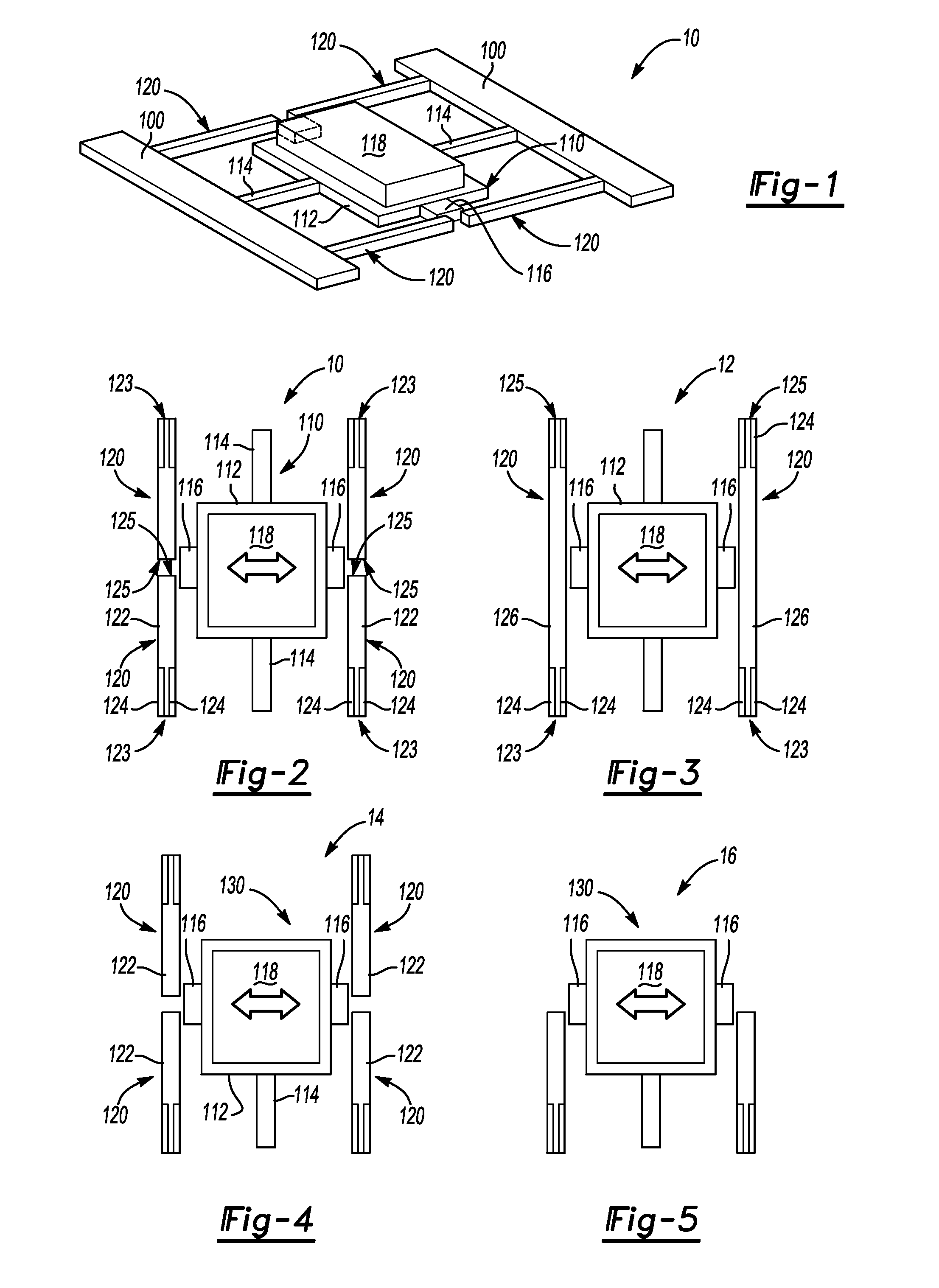
[0047]An alternative embodiment 12 as shown in FIG. 3 can include a low frequency element 110 that is identical and / or similar to the embodiment shown in FIG. 2 with one or more high frequency beams 126. The high frequency beams 126 have a first end 123 and a second end 125 that are both attached to the base 100. Stated differently, the high frequency beam 126 does not have a free end as does the high frequency beam 122 shown in FIG. 2. Similar to the high frequency beam 122, a piezoelectric strip 124 can be rigidly attached to the beam 126 proximate to the first end 123. In addition, a piezoelectric strip 124 can be attached to the beam 126 proximate to the second end 125. It is appreciated that the low frequency element 110 can contact the high frequency beam 126 and afford for its vibration at a resonant frequency and bending movement of the piezoelectric strip 124. As shown in FIG. 3, a first high frequency beam 126 can be located on one side of the low frequency element 110 and...

embodiment 40

[0051]Turning now to FIGS. 13 and 14, embodiment 40 illustrates an energy harvesting device where movement of the low frequency element 110 can be out-of-plane and yet is taken advantage of with the use of a piezoelectric film 103 and / or 105 that are located out-of-plane relative to the low frequency element 110. In particular, FIGS. 13 and 14 illustrate the use of the piezoelectric film 103 and / or 105 in combination with a lower cover 102 and / or an upper cover 104, respectively, in a manner such that out-of-plane movement of the low frequency element 110 can impact the piezoelectric film(s), the impact causing elastic deformation thereof and thus generation of a voltage differential. In this manner, random vibration of a parent component that results in two-dimensional movement of the low frequency element can be taken advantage of.

[0052]FIGS. 15 and 16 illustrate embodiments 60 and 70, respectively, where two-dimensional movement of the low frequency element 110 is taken advantage...


PUM


Abstract

The present invention discloses an energy harvesting device that converts small magnitude and low frequency vibrations into electrical energy. The device can include a base, a low frequency element, and a piezoelectric element. The low frequency element can be movably attached to the base and the piezoelectric element can also be attached to the base and be spaced apart from the low frequency element with a vacant space therebetween. Upon vibration of the low frequency element resulting from environmental vibrations, the low frequency element can impact the piezoelectric element and cause elastic deformation thereto.

Description

FIELD OF THE INVENTION[0001]The present invention relates to an energy harvesting device and, in particular, an energy harvesting device that can convert environmental vibrations to electrical energy.BACKGROUND OF THE INVENTION[0002]The conversion or scavenging of environmental vibration to voltage differential can provide free and clean energy. In addition, environmental vibration is present in a multitude of operations, activities, and the like, and such vibrations are not significantly influenced by environmental conditions such as temperature, humidity, amount of sunlight, etc. As such, environmental vibration is one of the most attractive power sources that can provide consistent power for extended periods of time.[0003]Vibration scavenging, also known as energy scavenging or energy harvesting, converts vibration to electrical energy using a piezoelectric material, the piezoelectric material converting mechanical strain into a voltage differential by creating a charge separatio...

Claims


Application Information

Patent Timeline
Patent Type & Authority Applications(United States)
IPC IPC(8): H02N2/18H01L41/22H01L41/23H01L41/39H01L41/45
CPCH01L41/1134H01L41/1136H02N2/186H10N30/304H10N30/306
Inventor YOON, SANG WONMARGOMENOS, ALEXANDROS
Owner TOYOTA MOTOR CO LTD
Why Eureka
Try Eureka