Magnetic field measuring apparatus

Inactive Publication Date: 2011-05-05
COLUMBIA PEAK VENTURES LLC
View PDF8 Cites 27 Cited by
  • Summary
  • Abstract
  • Description
  • Claims
  • Application Information

AI Technical Summary

Benefits of technology

[0009]An advantage of some aspects of the invention is that a technology is provided in which the precision of the measuring of the magnetic field gradient using the light pumping method can be improved.
[0011]According to an aspect of the invention, even if the polarization rotation angle is small with respect to the strength of the magnetic field in each of the regions, the probe lights pass through a number of times with respect to the magnetic medium in each of the regions so that the polarization rotation angle that is detected is large and the measuring precision of the magnetic field gradient can be improved. Also, even though the polarization rotation angle may be small in one through passage, the density of the magnetic medium becomes small so that the absorption of the probe light can be small and the measuring precision of the magnetic field gradient can be further improved.

Problems solved by technology

However, the measuring precision may be low when the strength of the magnetic field and the polarization rotation angle of the probe light are not in a proportionate relation.
Therefore, there is a need to use an expensive magnetic shield.

Method used


Image

  • Magnetic field measuring apparatus
  • Magnetic field measuring apparatus
  • Magnetic field measuring apparatus

Examples


embodiments

Overall Configuration

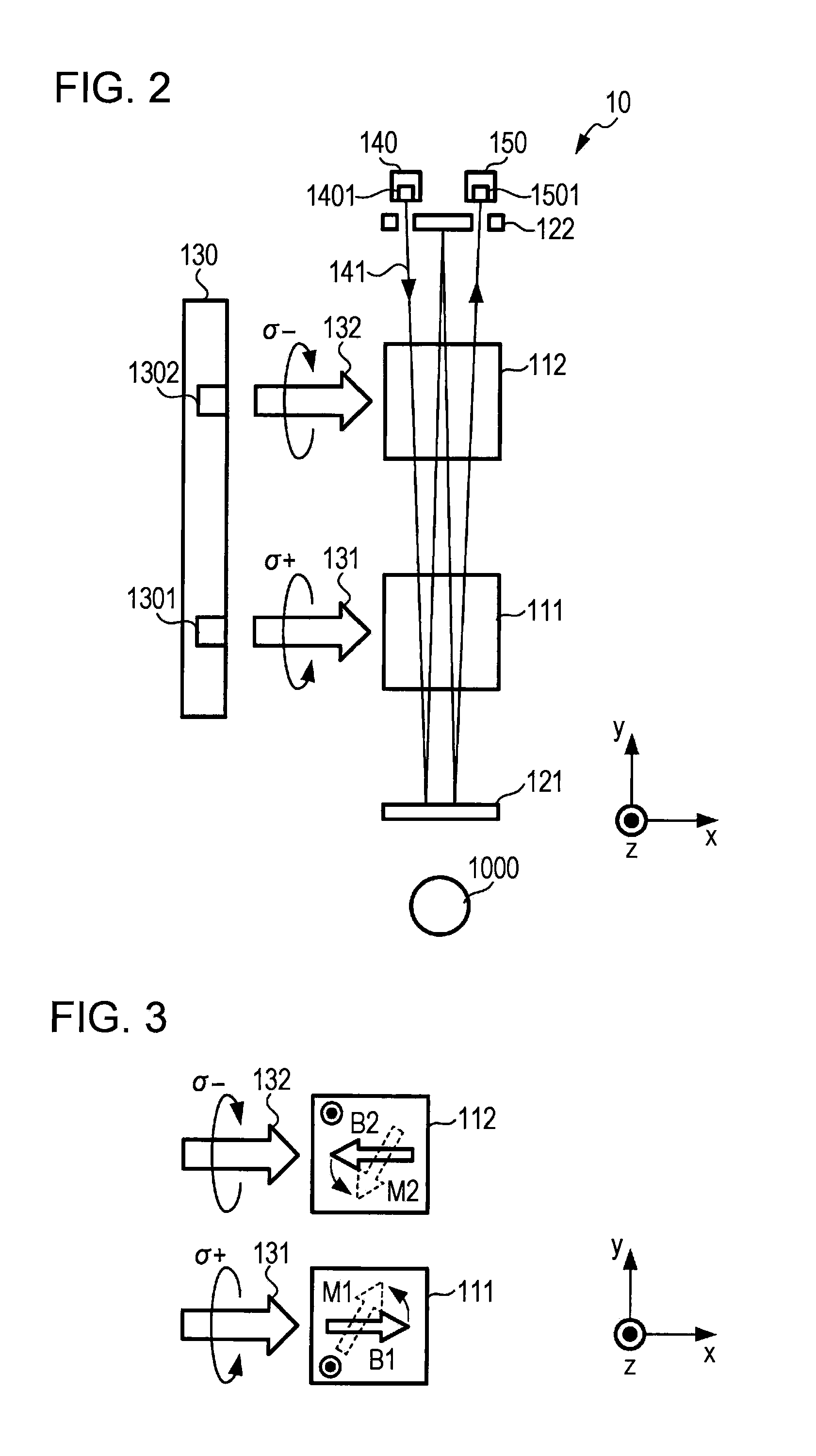
[0030]FIG. 1 is a block diagram showing a configuration of a magnetic field measuring apparatus 1. The magnetic field measuring apparatus 1 is an apparatus that measures the strength of a magnetic field that is generated from an object being measured using a light pumping method, and has the measuring section 10, the control section 11, the storing section 12, the display section 13, the operation section 14 and the interface 15. The measuring section 10 has each of the configurations that measures the strength of the magnetic field and performs control of the measuring start and finish by the control section 11. The measuring section 10 outputs polarized light rotation angle information to the control section 11 during measuring. Description will be given below regarding the detail of the measuring section 10 and the polarized light rotation angle information.

[0031]The control section 11 has an arithmetic processing circuit such as CPU (Central Processing Unit)...

modified embodiment

[0081]As described above, description has been given concerning the embodiment of the invention, however the invention can be modified in various examples as described below.

first modified example

[0082]In the above-described embodiment, the ejecting section 1401 and the light receiving section 1501 are positioned in the same side with respect to the first gas cell 111 and the second gas cell 112, however they may be positioned in different sides to each other.

[0083]FIG. 7 is a drawing showing a configuration of a measuring section 10A according to a first modified example. The measuring section 10A uses the reflecting mirrors 121A and 122A instead of the reflecting mirrors 121 and 122 of the measuring section 10 in the embodiment, and the position of the light receiving section 1501 is on the side opposite to the position of the ejecting section 1401 through the first gas cell 111 and the second gas cell 112.

[0084]In the case of this configuration, the relation between positive and negative of the y-axis direction is different when the light receiving section 1501 receives the probe light 141, so that the process is performed reversing positive and negative as the above-desc...


PUM


Abstract

A beam that passes through a plurality of gas cells a number of times is led to a deflection meter from a light ejecting section, detection of a deflected surface angle is performed and a strength of a magnetic field is measured by a structure in which the plurality of the gas cells is arranged along a light beam between two reflection units or light concentrating units that have a light beam incidence section and a light beam ejecting section and are opposite to each other, and a laser beam that is incident from the light beam incidence section passes through the plurality of the gas cells and then is multiply reflected by both reflection units.

Description

CROSS-REFERENCE TO RELATED APPLICATIONS[0001]The entire disclosure of Japanese Patent Application No. 2009-249436, filed Oct. 29, 2009 is expressly incorporated by reference herein.BACKGROUND[0002]1. Technical Field[0003]The present invention relates to a technology that measures the strength of a magnetic field.[0004]2. Related Art[0005]As the technology that measures the strength of a magnetic field, an atom magnetization sensor that uses an electronic spin polarization of alkali metal gas is suggested. When a pump light of a circular polarized light is irradiated with respect to a cell in which an alkali metal vapor is present and a probe light of the straight polarized light passes through the cell, the polarized light surface of the probe light rotates according to the strength of the magnetic field that is applied to the cell. Thus, the strength of the magnetic field is measured by detecting a polarization rotation angle of the probe light.[0006]A technology has been developed...

Claims


Application Information

Patent Timeline
IPC IPC(8): G01R33/02
CPCG01R33/0322G01R33/26G01R33/24G01R33/0327G01R33/032
Inventor NAGASAKA, KIMIO
Owner COLUMBIA PEAK VENTURES LLC
Why Eureka
Try Eureka