Electronic component

a technology of electronic components and components, applied in the direction of transformer/inductance details, printed inductances, inductances, etc., can solve the problems of difficult to obtain high q value, reducing the resonance frequency of the coil, and difficulty in obtaining high q value, etc., to achieve high q value and high inductance value

Active Publication Date: 2011-05-05
MURATA MFG CO LTD
View PDF0 Cites 36 Cited by
  • Summary
  • Abstract
  • Description
  • Claims
  • Application Information

AI Technical Summary

Benefits of technology

[0011]To overcome the problems described above, preferred embodiments of the present invention provide an electronic component that has a high inductance value and a high Q value.
[0013]With various preferred embodiments of the present invention, a high inductance value and a high Q value are obtained.

Problems solved by technology

When such floating capacitances occur, there is a problem in that the resonant frequency of the coil is decreased and the Q value at a frequency at which the coil is to be used is decreased.
However, there is a problem with the electronic component 500 illustrated in FIG. 7 in that it is difficult to obtain a high Q value.
However, in the multilayer inductor disclosed in Japanese Unexamined Patent Application Publication No. 9-63848, two coils are arranged in parallel with each other and, therefore, the same problem as that described with respect to the electronic component 500 illustrated in FIG. 7 occurs.
Furthermore, since external electrodes are provided on side surfaces of the multilayer body, the multilayer inductor described in Japanese Unexamined Patent Application Publication No. 9-63848 also has the problem of the Q value being decreased due to the increased floating capacitance.

Method used


Image

  • Electronic component
  • Electronic component
  • Electronic component

Examples


first preferred embodiment

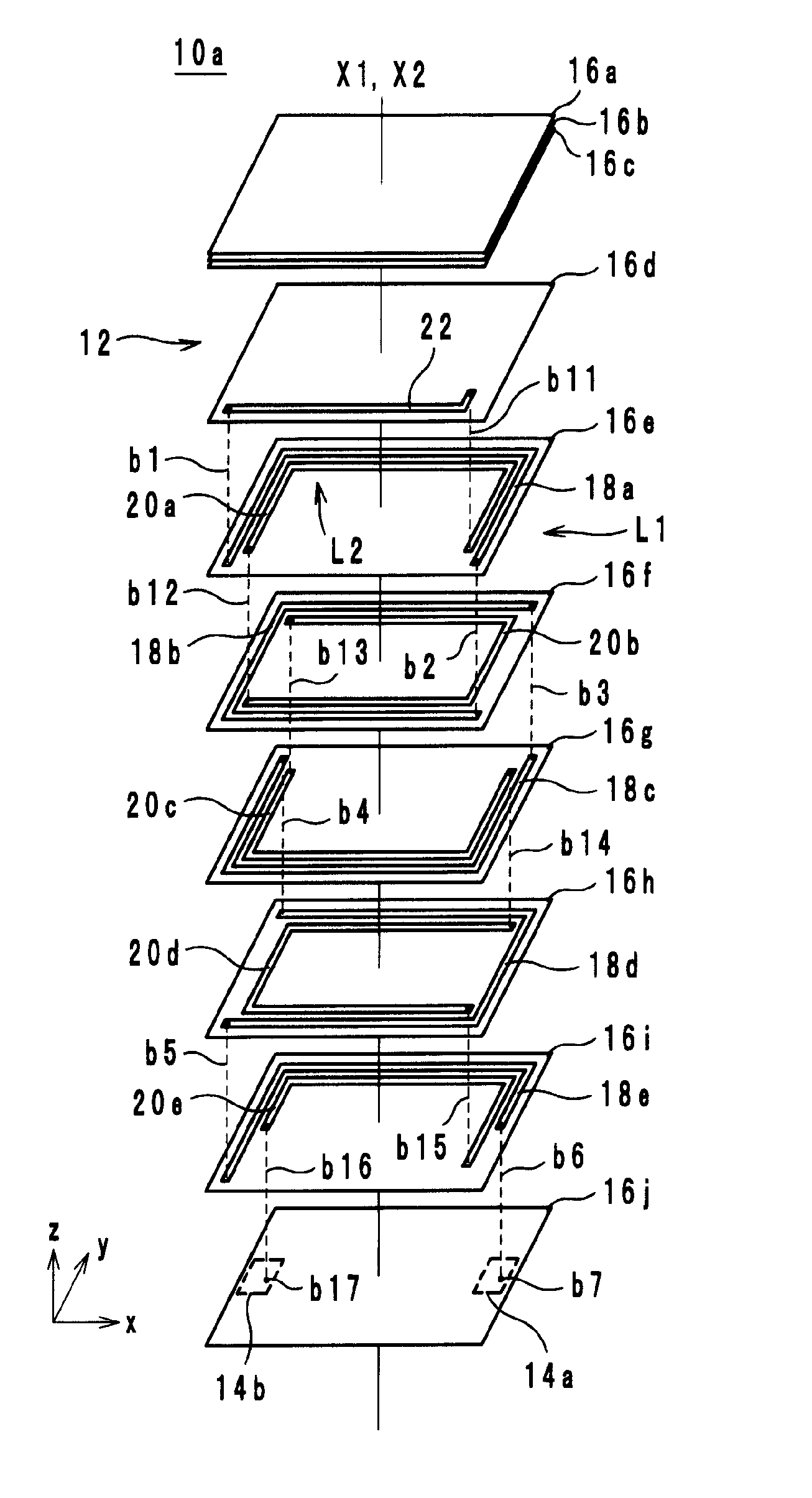
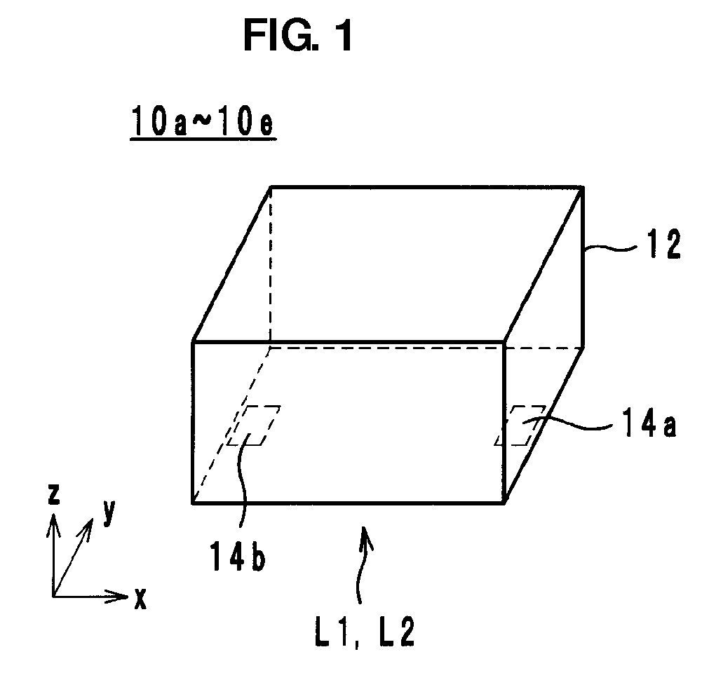
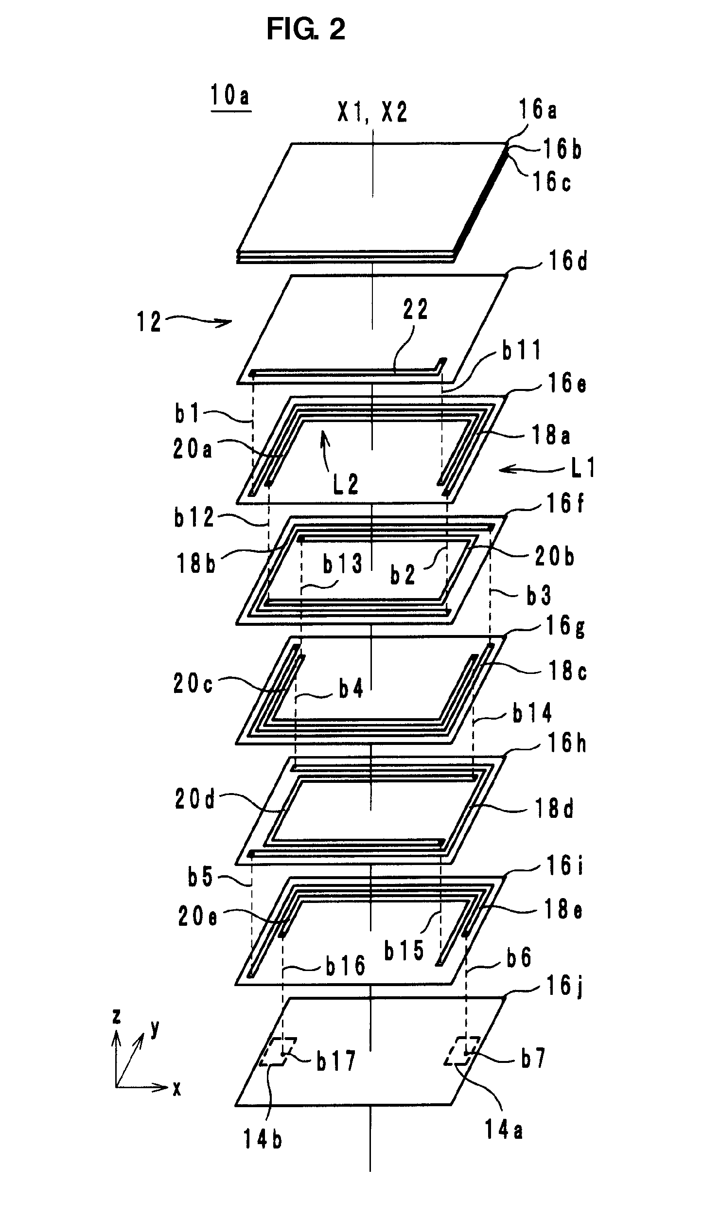
[0023]FIG. 1 is an external perspective view of an electronic component 10a according to a first preferred embodiment of the present invention. FIG. 2 is an exploded perspective view of the electronic component 10a according to the first preferred embodiment of the present invention. Hereafter, the stacking direction of the electronic component 10a is defined as a z-axis direction, a direction in which longer edges of the electronic component 10a extend is defined as an x-axis direction, and a direction in which shorter edges of the electronic component 10a extend is defined as a y-axis direction. The x-axis, the y-axis, and the z-axis are orthogonal to one another.

[0024]As illustrated in FIG. 1, the electronic component 10a includes a multilayer body 12 and external electrodes 14a and 14b. The multilayer body 12 preferably has a substantially rectangular parallelepiped shape and includes coils L1 and L2 provided therein, for example. The external electrode 14a is electrically conne...

second preferred embodiment

[0050]Hereafter, an electronic component 10b according to a second preferred embodiment of the present invention will be described with reference to the drawings. FIG. 3 is an exploded perspective view of the electronic component 10b according to the second preferred embodiment. Hereafter, the stacking direction of the electronic component 10b is defined as a z-axis direction, a direction in which longer edges of the electronic component 10b extend is defined as an x-axis direction, and a direction in which shorter edges of the electronic component 10b extend is defined as a y-axis direction. The x-axis, the y-axis, and the z-axis are orthogonal to one another. Furthermore, FIG. 1 shows an external perspective view of the electronic component 10b.

[0051]As illustrated in the electronic component 10b, the connection electrode 22 may preferably circle around the coil axes X1 and X2. As a result of the connection electrode 22 circling around the coil axes X1 and X2 in this manner, a hi...

third preferred embodiment

[0052]Hereafter, an electronic component 10c according to a third preferred embodiment of the present invention will be described with reference to the drawings. FIG. 4 is an exploded perspective view of the electronic component 10c according to the third preferred embodiment. Hereafter, the stacking direction of the electronic component 10c is defined as a z-axis direction, a direction in which longer edges of the electronic component 10c extend is defined as an x-axis direction, and a direction in which shorter edges of the electronic component 10c extend is defined as a y-axis direction. The x-axis, the y-axis, and the z-axis are orthogonal to one another. Furthermore, FIG. 1 shows an external perspective view of the electronic component 10c.

[0053]As illustrated in the electronic component 10c, each of the coil electrodes 20a to 20e that define the coil L2 preferably have a length of a plurality of turns. Thus, the amount of magnetic flux generated around the individual coil ele...


PUM

PropertyMeasurementUnit
floating capacitancesaaaaaaaaaa
resonant frequencyaaaaaaaaaa
frequencyaaaaaaaaaa

Abstract

In an electronic component, a multilayer body includes a plurality of insulator layers stacked on top of one another. A first coil is provided in the multilayer body, includes a first coil axis and extends toward the positive side in the z-axis direction while circling counterclockwise around the first coil axis. A second coil is connected to the first coil, is provided in the multilayer body, includes a second coil axis, and extends toward the negative side in the z-axis direction while circling counterclockwise around the second coil axis. When viewed in plan from the z-axis direction, the first coil axis is disposed inside the second coil and the second coil axis is disposed inside the first coil.

Description

BACKGROUND OF THE INVENTION[0001]1. Field of the Invention[0002]The present invention relates to electronic components, and more particularly, to electronic components including built-in coils.[0003]2. Description of the Related Art[0004]The multilayer coil component described in Japanese Unexamined Patent Application Publication No. 10-270249 is a known example of an existing electronic component. In this multilayer coil component, a multilayer body having a rectangular parallelepiped shape is formed of a plurality of insulating green sheets stacked on top of one another. Coil conductors are provided on the plurality of insulating green sheets. The coil conductors are connected to one another through via holes, thereby forming a helical coil. Furthermore, two terminal electrodes are arranged so as to cover two side surfaces of the multilayer body and the helical coil is connected to two terminal electrodes.[0005]In the multilayer coil component described in Japanese Unexamined Pate...

Claims


Application Information

Patent Timeline
Patent Type & Authority Applications(United States)
IPC IPC(8): H01F5/00
CPCH01F17/0013H01F2017/0073H01F2017/004H01F27/006H01F27/2804H01F2027/2809
Inventor MATSUSHITA, YOSUKE
Owner MURATA MFG CO LTD
Why Eureka
Try Eureka