Carriage device and inkjet device

a technology of inkjet printer and carriage device, which is applied in the direction of inking apparatus, printing, power drive mechanism, etc., can solve the problems of troublesome attachment and detachment of head units, increased apparatus size, and troublesome working orientation, and achieves smooth installation and short time

Inactive Publication Date: 2011-05-05
SEIKO EPSON CORP
View PDF3 Cites 26 Cited by
  • Summary
  • Abstract
  • Description
  • Claims
  • Application Information

AI Technical Summary

Benefits of technology

[0040]Through this configuration, the head unit can be simply and smoothly installed in the carriage at various angles in the peripheral direction of the rotary drum. Consequently, the head units of a plurality of carriage devices can be replaced in a short time.

Problems solved by technology

A large space for attachment and detachment is therefore required on top of the setting stage, and the size of the apparatus increases.
In cases in which the head unit is mounted in a high position or at various angles not parallel to the floor surface, the working orientation is unstable, and the head unit is troublesome to attach and detach.

Method used


Image

  • Carriage device and inkjet device
  • Carriage device and inkjet device
  • Carriage device and inkjet device

Examples


Embodiment Construction

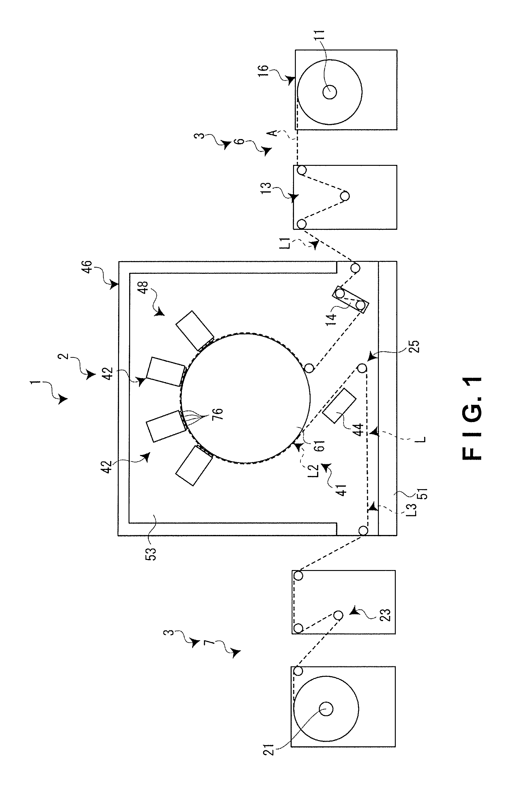
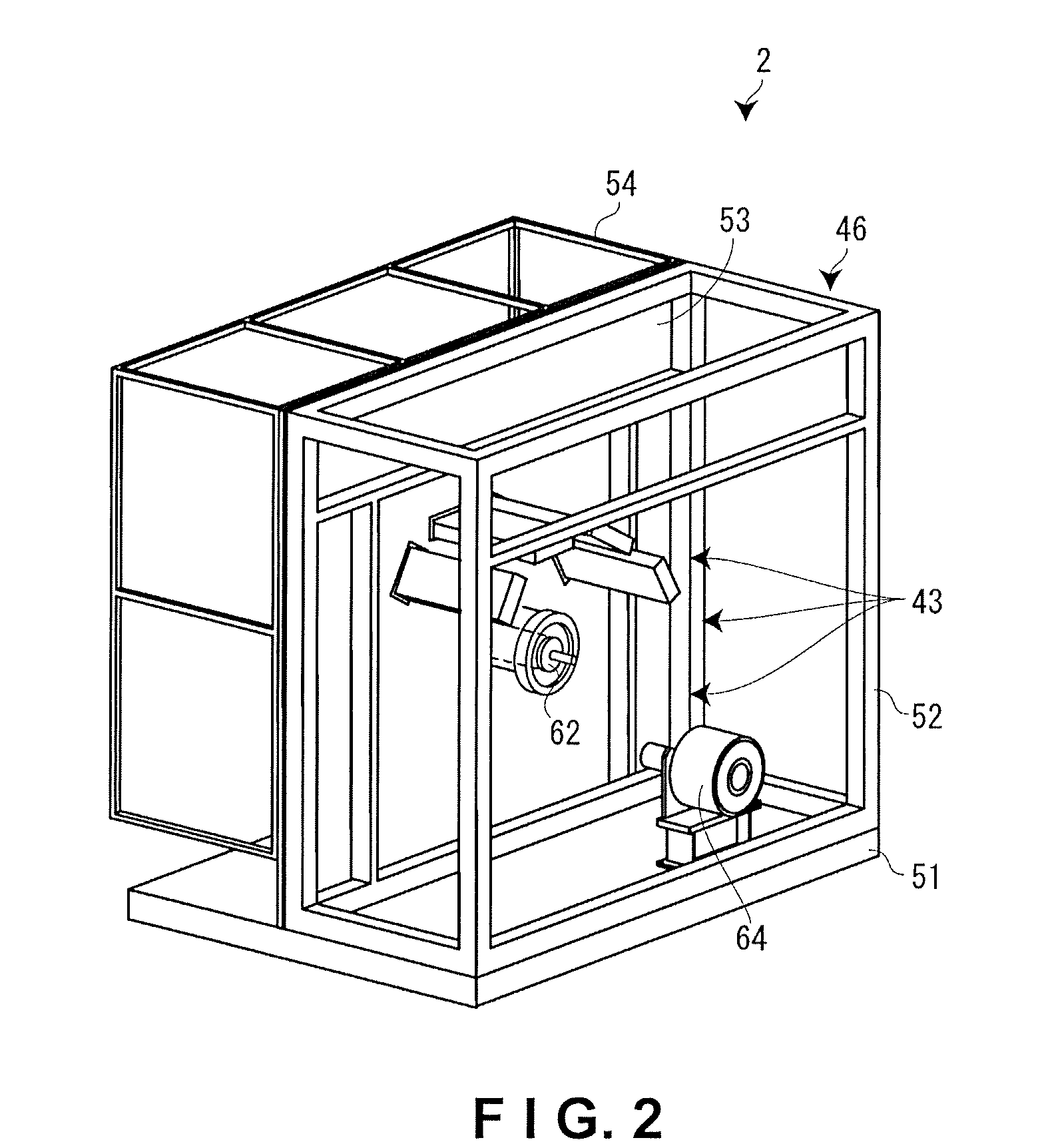
[0050]The inkjet device according to an embodiment of the present invention will be described with reference to the accompanying drawings. This inkjet device is a center drum-type printing device in which a plurality of inkjet heads is arranged in the peripheral direction, and uses a UV ink (ultraviolet-curing ink) to print on a long recording medium which is fed reel to reel. The recording medium is a label film, paper, or other sheet, for example, and media of various widths and thicknesses can be printed on. In the following description, the direction through the paper surface in FIG. 1 is the front-rear direction, where the forward side is “front,” and the inward side is “rear.” Specifically, the direction in which the rotational axis (drum shaft 62) of the rotary drum 61 described hereinafter extends is the front-rear direction, the direction from the drum motor 64 described hereinafter to the rotary drum 61 is the forward direction (forward side), and the direction from the ro...


PUM


Abstract

A carriage device includes a head unit, a printing head and a carriage. The head unit has a sub-plate attached to a head plate via an adjustment mechanism. The printing head is attached to the head plate via the sub-plate. The carriage retains the head unit. The adjustment mechanism includes a first-direction adjustment plate, a rotation position adjustment plate, and a pitch angle adjustment plate. The first-direction adjustment plate adjusts a position of the sub-plate with respect to the head plate in a first direction. The rotation position adjustment plate adjusts, in a predetermined plane, a rotation position of the sub-plate with respect to the head plate about a rotational axis that is normal to the predetermined plane. The pitch angle adjustment plate adjusts a pitch angle of the sub-plate with respect to the head plate, the pitch angle being in relation to the predetermined plane.

Description

CROSS-REFERENCE TO RELATED APPLICATIONS[0001]This application claims priority to Japanese Patent Application No. 2009-248496 filed on Oct. 29, 2009. The entire disclosure of Japanese Patent Application No. 2009-248496 is hereby incorporated herein by reference.BACKGROUND[0002]1. Technical Field[0003]The present invention relates to a carriage device and inkjet device in which a head unit is installed having a plurality of droplet discharge heads mounted therein.[0004]2. Related Art[0005]In a conventional large-size printer, a large-size head unit in which numerous droplet discharge heads are mounted in a single carriage (head plate) is required, and the large-size head unit requires replacement. In order to efficiently transport and position such a large-size carriage, a head unit is known which is provided with a plurality of droplet discharge heads, a carriage in which the plurality of droplet discharge heads is mounted so as to protrude on the back surface, and a pair of left and...

Claims


Application Information

Patent Timeline
Patent Type & Authority Applications(United States)
IPC IPC(8): B41J23/00B41J11/22
CPCB41J2/155B41J2/2146B41J2202/20B41J2202/19B41J25/308B41J2025/008
Inventor WANIBE, AKIHISA
Owner SEIKO EPSON CORP
Why Eureka
Try Eureka