Method for using a fixator device

a fixator and device technology, applied in the field of fixator devices, can solve the problems of complex set of multiple and potentially endless configurations, gross manipulation of the device as a whole, and the need to loosen the joints of the device, so as to reduce or eliminate the

Inactive Publication Date: 2011-05-05
SIXFIX
View PDF80 Cites 35 Cited by
  • Summary
  • Abstract
  • Description
  • Claims
  • Application Information

AI Technical Summary

Benefits of technology

[0010]The present invention provides a method for transforming readily available orthopedic data into parameters to configure a fixator to achieve a needed or desired orientation of the bone segments, by solving a system of simultaneous equations represented by a kinematic chain for a fixator device that provides six degrees of freedom of movement, either an open kinematic or close

Problems solved by technology

This approach requires the frame to be constructed based on the deformity present, resulting in a fairly straightforward method of use but a potentially complex set of multiple and potentially endless configurations.
Typically these devices can be used to fix bone segments in a particular orientation but not to gradually adjust the orientation, since the joints of the device do not have a direct adjustment device associated with each

Method used


Image

  • Method for using a fixator device
  • Method for using a fixator device
  • Method for using a fixator device

Examples


Embodiment Construction

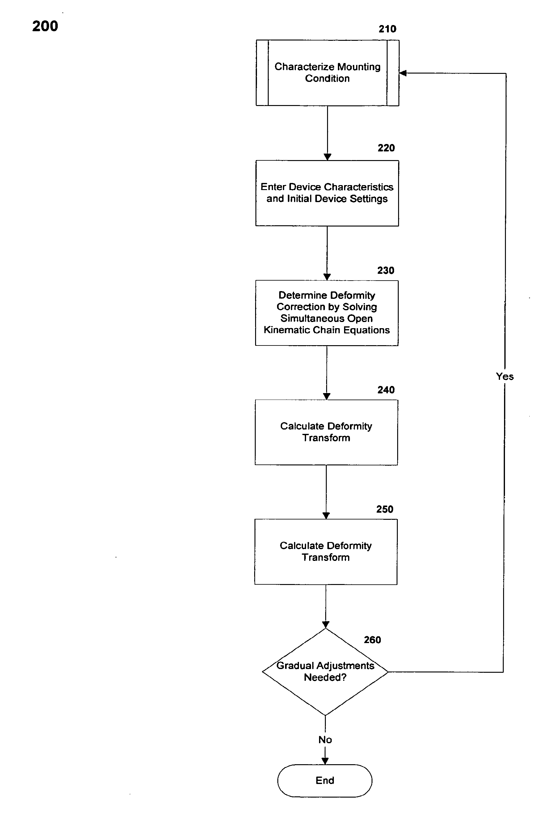
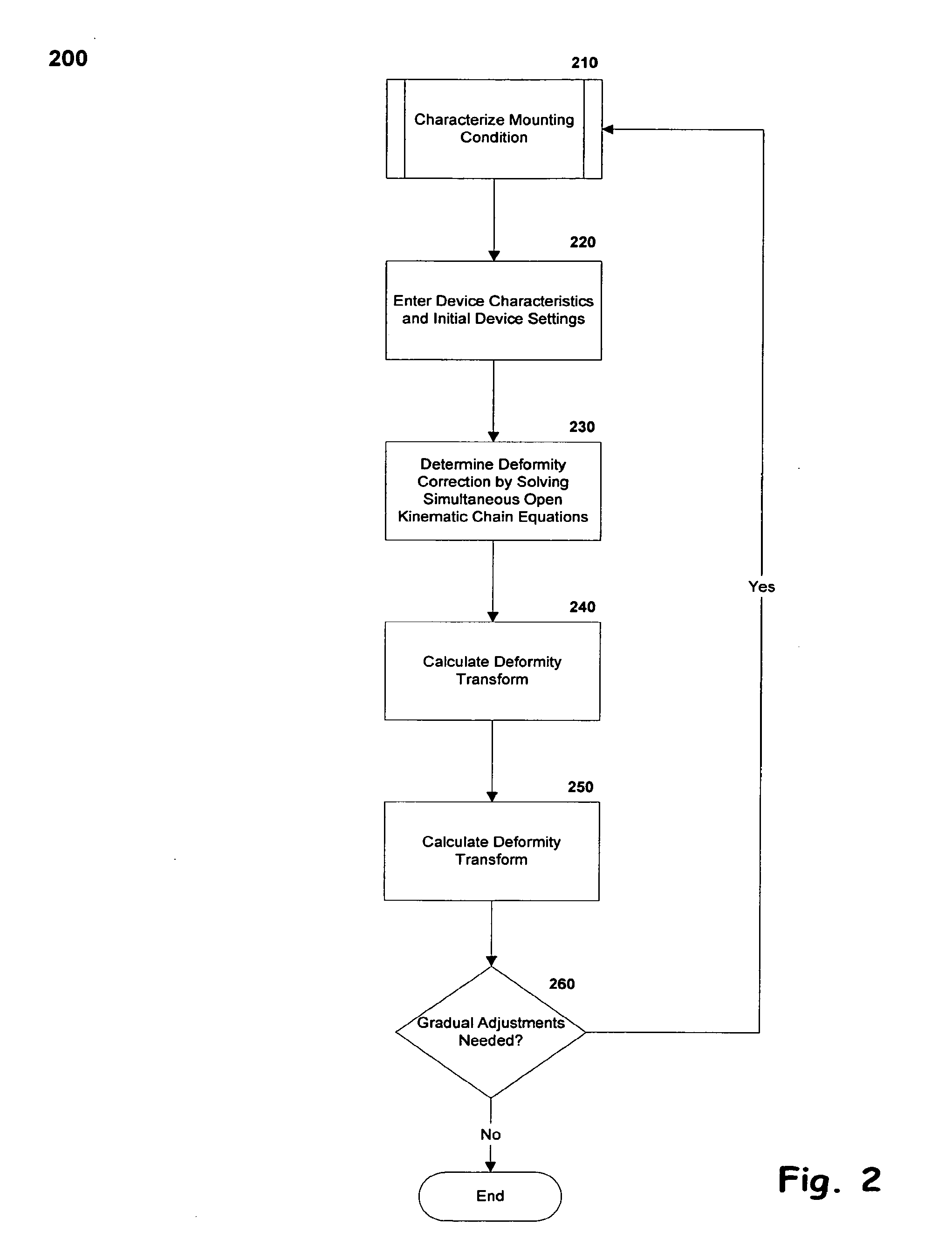
[0041]Exemplary embodiments of the present invention provide a method for defining the manipulation of a fixator device and for characterizing tissue, such as bone fragments, which may be acted upon by the fixator.

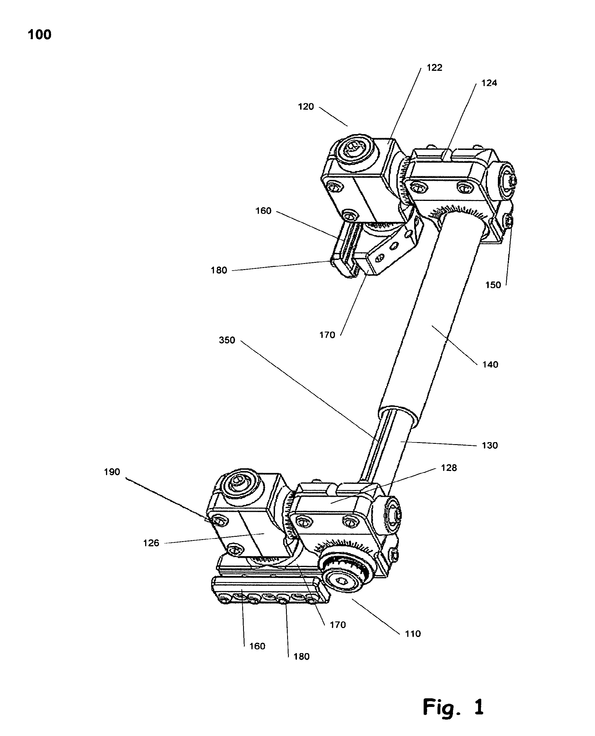
[0042]FIG. 1 provides an isomeric image of an exemplary unilateral fixator 100 that may be manipulated using the method of the present invention. Referring to FIG. 1 a first compound movable joint 110 is attached to an extension strut 130 and a second compound movable joint 120 is attached to a base strut 140. These two compound movable joints 110, 120 are identical. The first compound movable joint 110 and second compound movable joint 120 each include two revolute joints 122, 124, 126, 128, the axes of which are orthogonally opposed. The second compound movable joint 120, also referred to herein as the ankle, is able to slide along, but not rotate about, the axis of the base strut 140. The first compound movable joint 110, also referred to herein as the wrist, is able to...


PUM


Abstract

A method for determining the proper configuration of a fixator or other medical device to correct a given deformity by solving the simultaneous equations representing the kinematic chain for the device. One skilled in the art would appreciate that x-rays, clinical evaluations, or a combination of both may be used to determine the distal and proximal mounting characteristics, including the use of digital x-rays with images from an imaging device to reduce or eliminate the needs for a physician to take measurements. The technique can be expanded to other medical evaluations. Additionally, one skilled in the art would appreciate that the method of the present invention could be written as one or more sets of instructions stored on a computer-readable medium that could be executed by a computer.

Description

STATEMENT OF RELATED PATENT APPLICATIONS[0001]This non-provisional patent application claims priority under 35 U.S.C. §119 to U.S. Provisional Patent Application No. 60 / 426,439, titled Unilateral Fixator Method, filed Nov. 14, 2002. This provisional application is hereby fully incorporated herein by reference.FIELD OF THE INVENTION[0002]The present invention relates to a method for using a fixator device and more specifically to developing a prescription for adjusting a fixator for deformity correction and for characterizing tissue through non-evasive methods.BACKGROUND OF THE INVENTION[0003]In orthopedic medicine, physicians often need to correct certain skeletal injuries or deformities with external fixator devices. These devices use pins or wires attached to the separate bone segments and an external structural frame to align, or fix, the bone segments in a way to aid in repairing the injury or correcting the deformity. Often the physician must gradually adjust the orientation of...

Claims


Application Information

Patent Timeline
IPC IPC(8): G06K9/00A61B17/56A61B17/64A61B17/66A61B19/00
CPCA61B17/6458A61B17/66A61B19/50A61B2019/5289A61B2017/564A61B2019/5238A61B2019/5268A61B19/52A61B34/10A61B90/36A61B2034/2068A61B2090/364A61B2090/376
Inventor MULLANEY, MICHAEL W.
Owner SIXFIX
Why Eureka
Try Eureka