Insert-molded ball joint

a ball joint and inserting technology, applied in the field of ball joints, can solve the problems of large rotational frictional torque of the ball stud with respect to the housing, increased and small resistance strength against the removal of the ball stud from the housing, so as to achieve the effect of minimizing play increasing the pull-out strength of the ball stud

Inactive Publication Date: 2011-05-05
CENT LTS +3
View PDF9 Cites 9 Cited by
  • Summary
  • Abstract
  • Description
  • Claims
  • Application Information

AI Technical Summary

Benefits of technology

[0010]Accordingly, the present invention has been made keeping in mind the above problems occurring in the prior art, and an object of the present invention is to provide an insert-molded ball joint which is configured such that rotational frictional torque of a ball stud is maintained under an appropriate level, pull-out strength of the ball stud is increased, and play of the ball stud is minimized.

Problems solved by technology

The technique of No. 10-0858689 has an advantage of a simple manufacturing process but is problematic in that because the housing is formed on the ball stud by direct injection molding, rotational frictional torque of the ball stud with respect to the housing is relatively large.
However, in the case of the ball joint of No. 10-0880844, resistance strength against a removal of the ball stud from the housing, in other words, pull-out strength, is relatively small.
Furthermore, because the entirety of the spherical head of the ball stud is installed in the housing by the ball seat, there is a problem in that play of the ball stud is increased.

Method used


Image

  • Insert-molded ball joint
  • Insert-molded ball joint
  • Insert-molded ball joint

Examples


Embodiment Construction

[0021]Hereinafter, a preferred embodiment of the present invention will be described in detail with reference to the attached drawings, such that those skilled in the art can easily implement the present invention. The present invention is realized in various manners and is not limited to the following embodiment. Furthermore, in the drawings, portions which are not related to the present invention should be omitted to explain the present invention more clearly. Reference should be made to the drawings, in which similar reference numerals are used throughout the different drawings to designate similar components.

[0022]In the specification, when the explanatory phrase “a part includes a component” is used, this means that the part may further include the component without excluding other components, so long as special explanation is not given.

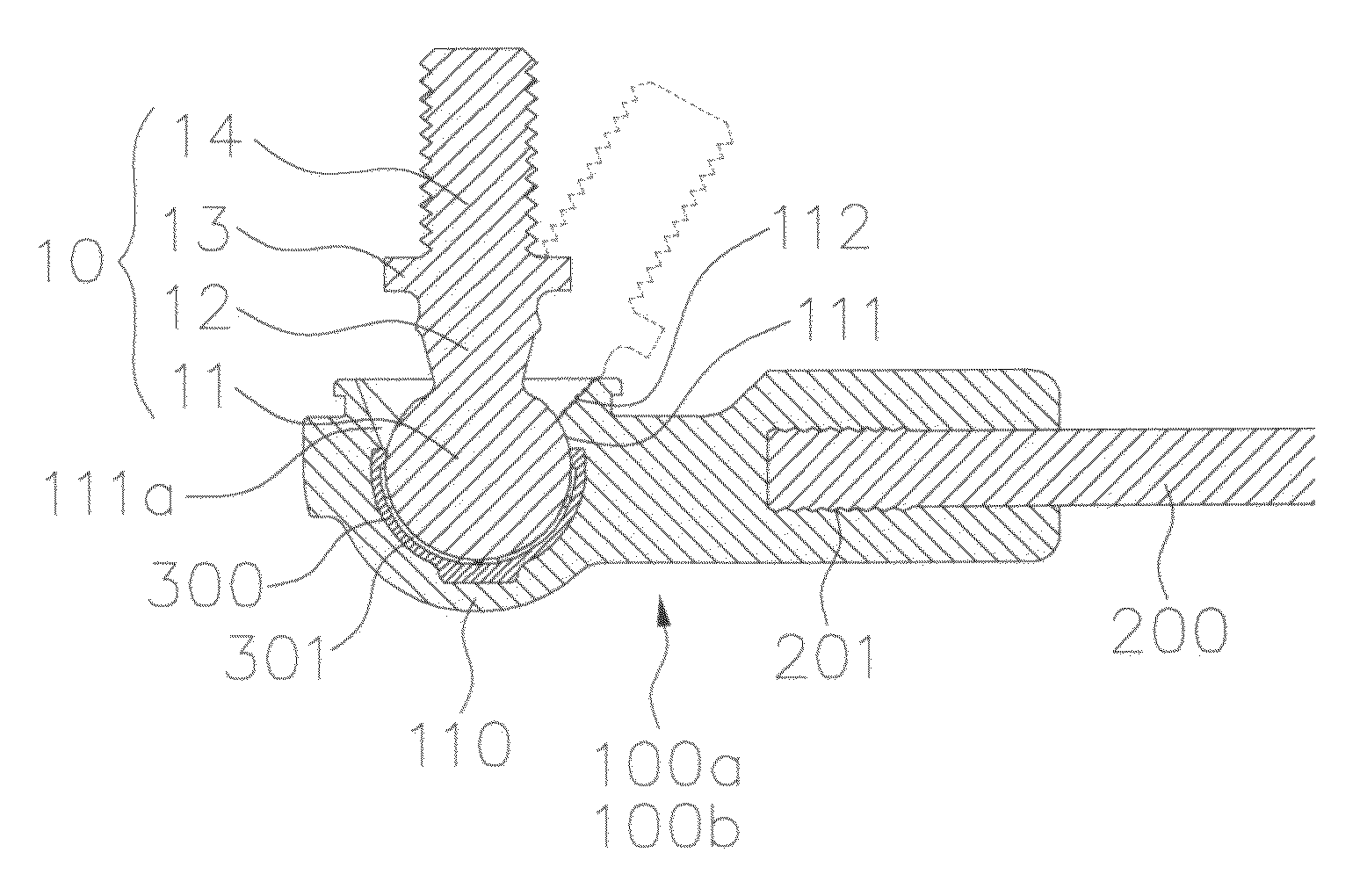
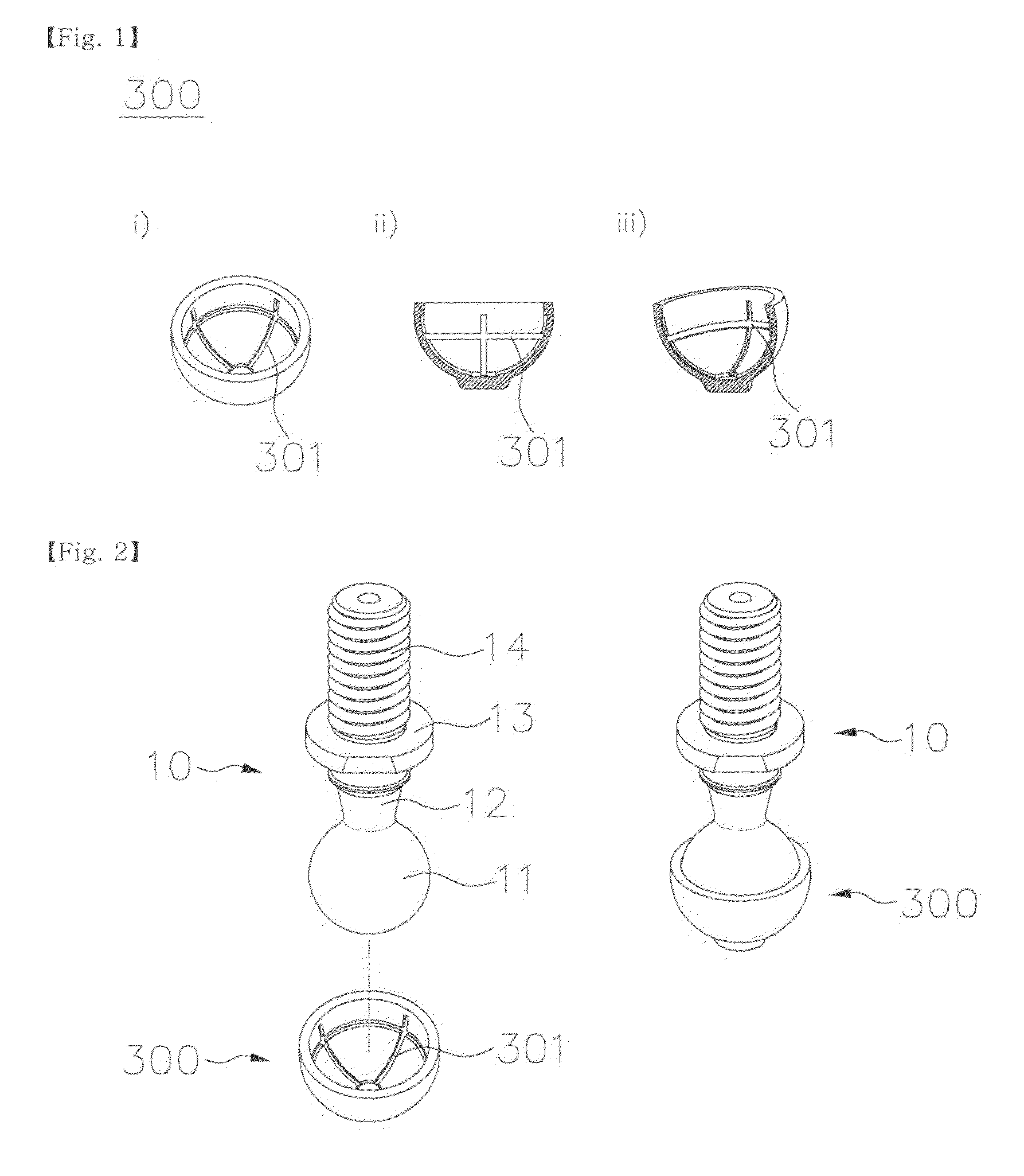
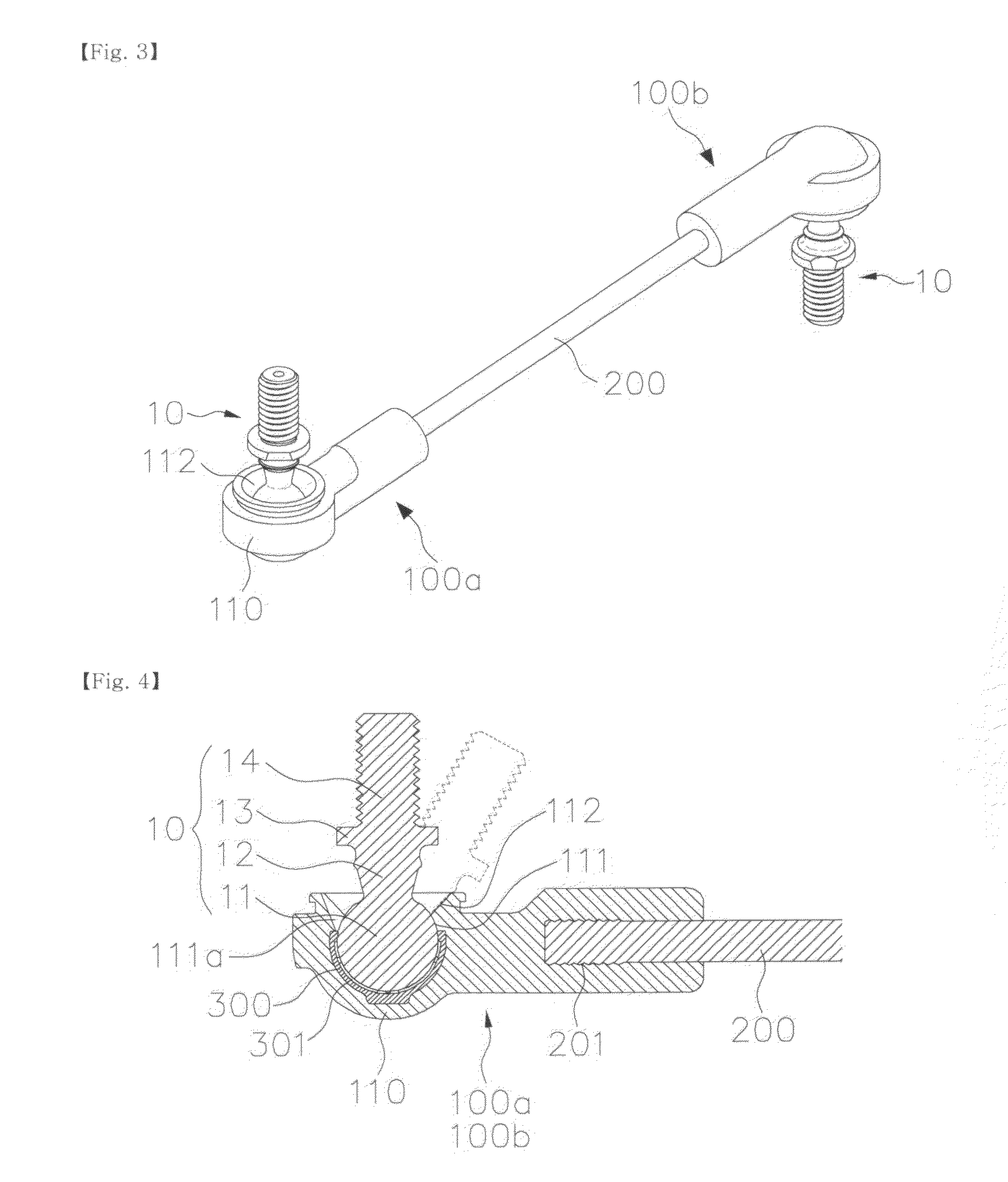
[0023]FIG. 1 is of a perspective view, a sectional view and a sectional perspective view showing a ball seat 300, according to an embodiment of...


PUM


Abstract

Disclosed herein is an insert-molded ball joint which is configured such that rotational frictional torque of a ball stud is kept below the appropriate level, pull-out strength of the ball stud is increased, and play of the ball stud is minimized. The ball stud has a spherical head. The spherical head of the ball stud is rotatably inserted into the ball seat. The housing covers the ball seat and a portion of the spherical head that is exposed from the ball seat. The upper end of the ball seat is disposed higher than the center of the spherical head. The housing includes a head support which covers the spherical head. A ball seat grease groove is formed in the inner surface of the ball seat. Housing grease grooves are formed in the head support in a vertical direction and meet the upper end of the ball seat.

Description

BACKGROUND OF THE INVENTION[0001]1. Field of the Invention[0002]The present invention relates generally to ball joints which are used in steering apparatuses or suspensions for vehicles and, more particularly, to a ball joint which is manufactured by insert molding.[0003]2. Description of the Related Art[0004]Generally, ball joints which are made only of metal and are manufactured in an assembly manner are widely used. Recently, insert-molded ball joints having housings made of synthetic resin have been proposed.[0005]As techniques relevant to the present invention, representative examples of an insert-molded ball joint were proposed by the applicant of the present invention in Korean Patent Registration No. 10-0858689 (date: Sept. 9, 2008) which was entitled “Insert-molded ball joint having grease grooves and method of manufacturing the same” and in Korean Patent Registration No. 10-0880844 (date: Jan. 21, 2009) which was entitled “Insert-molded ball joint and method of manufacturi...

Claims


Application Information

Patent Timeline
Patent Type & Authority Applications(United States)
IPC IPC(8): F16C11/06
CPCF16C11/0638F16C11/068Y10T403/32647Y10T403/32737Y10T403/32721Y10T403/32795Y10T403/32655Y10T403/32663F16C2326/24F16C2326/05F16C11/06F16C11/00
Inventor SEOL, SANG HOONWOO, YOUNG MANSUNG, GI YONG
Owner CENT LTS
Why Eureka
Try Eureka