Fuel pump with an improved damping device for a direct injection system

a technology of direct injection and damping device, which is applied in the direction of fuel injecting pump, machine/engine, positive displacement liquid engine, etc., can solve the problems of inability to guarantee, rate pulsation may produce noise at an audible frequency, and tight damping body

Active Publication Date: 2011-05-05
MARELLI EURO SPA
View PDF1 Cites 22 Cited by
  • Summary
  • Abstract
  • Description
  • Claims
  • Application Information

AI Technical Summary

Problems solved by technology

The fuel flow rate pulsations may produce noise at an audible frequency, which may be annoying for occupants of a vehicle which uses the fuel pump; furthermore, the fuel pressure oscillations may damage a low-pressure pump which draws the fuel from a tank for feeding the fuel itself to the high-pressure pump intake.
However, it has been observed that the mechanical structure of the damping device EP1500811B1 does not guarantee over time the tightness of the damping bodies which tend to be subject to a gradual loss of pressure of the gas contained in the closed chambers defined within the damper bodies themselves.

Method used


Image

  • Fuel pump with an improved damping device for a direct injection system
  • Fuel pump with an improved damping device for a direct injection system
  • Fuel pump with an improved damping device for a direct injection system

Examples


Embodiment Construction

[0007]It is the object of the present invention to provide a fuel pump for a direct injection system, which fuel pump is free from the above-described drawbacks and which is easy and cost-effective to make.

[0008]According to the present invention, a fuel pump for a direct injection system is made as disclosed in the attached claims.

BRIEF DESCRIPTION OF THE DRAWINGS

[0009]The present invention will now be described with reference to the accompanying drawings, which set forth some non-limitative embodiments thereof, in which:

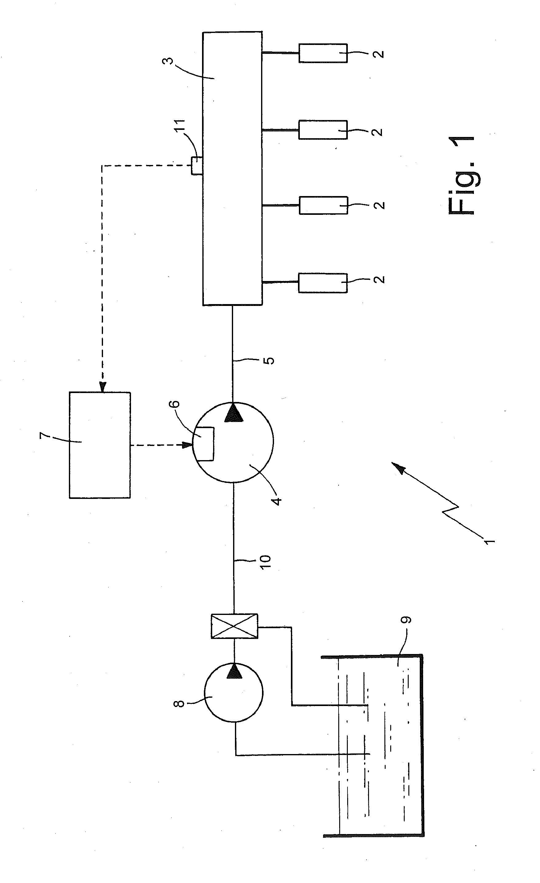
[0010]FIG. 1 is a diagrammatic view with parts removed for clarity of a direct fuel injection system of the common rail type;

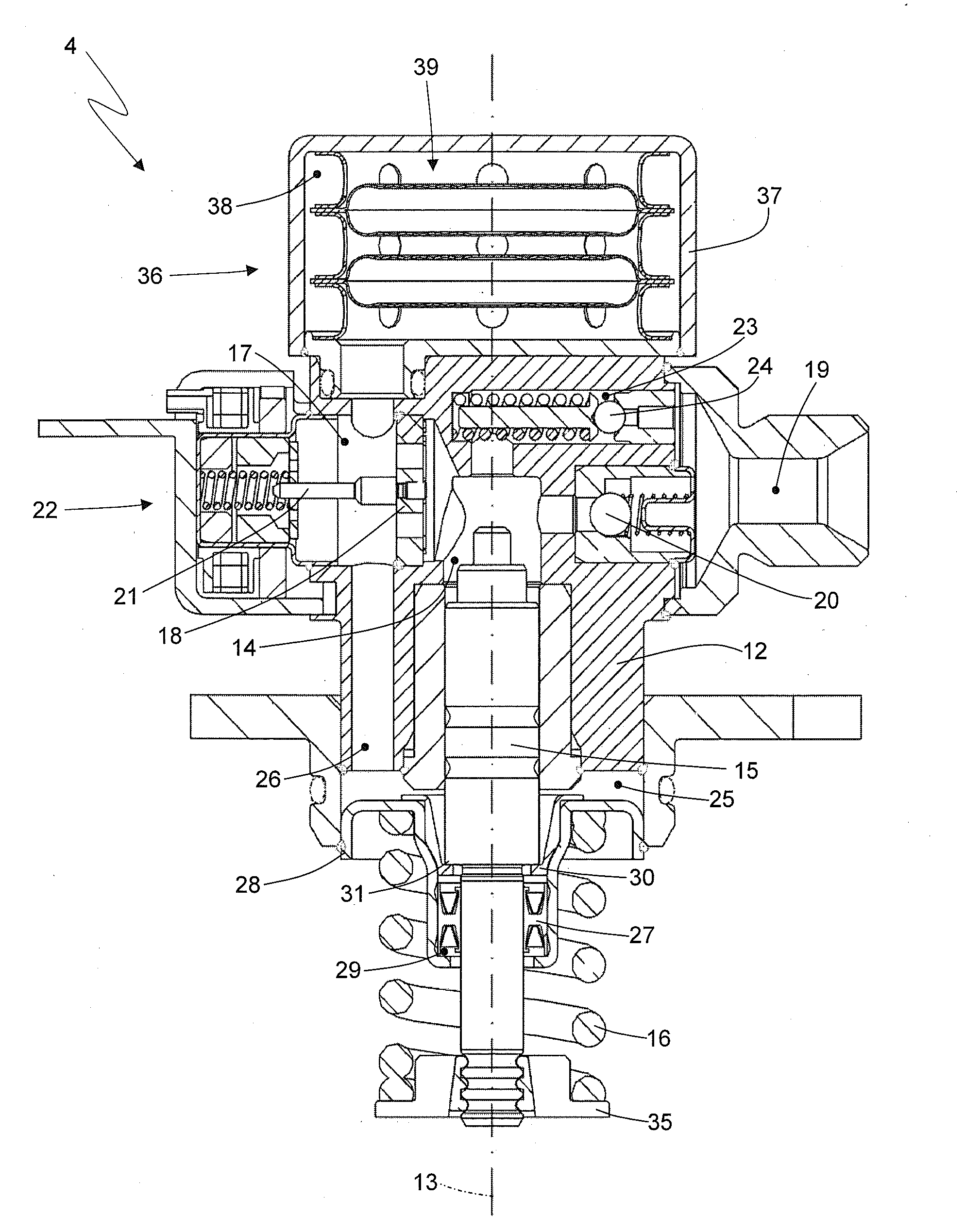
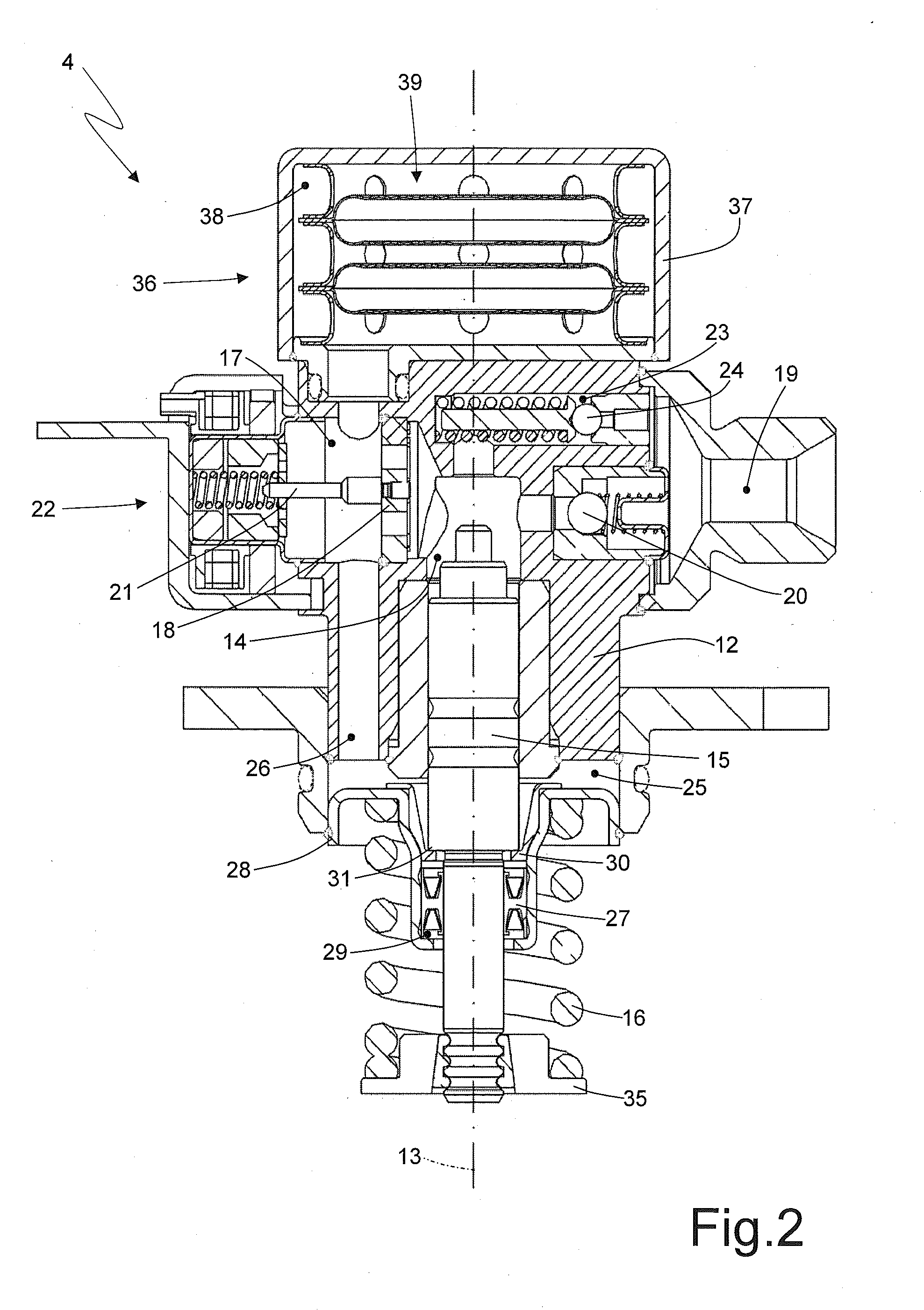
[0011]FIG. 2 is a diagrammatic, section view, with parts removed for clarity, of a high-pressure fuel pump of the direct injection system in FIG. 1;

[0012]FIG. 3 is a view on enlarged scale of a different embodiment made according to the present invention of a damping device of the high-pressure pump in FIG. 2;

[0013]FIG. 4 is an enlarged scale...


PUM


Abstract

A fuel pump for a direct injection system having: at least one pumping chamber; a piston which is mounted sliding inside the pumping chamber in order to vary cyclically the volume of the pumping chamber; an intake duct connected to the pumping chamber and regulated by an inlet valve; a delivery duct connected to the pumping chamber and regulated by a one-way delivery valve which allows exclusively a fuel flow outgoing from the pumping chamber; and a damping device, which is placed along the intake duct upstream of the inlet valve, and comprises at least one elastically deformable damping body that has internally a closed chamber filled with pressurized gas and composed of two metal plates cup shaped and welded together at their annular edges by an annular weld without interruptions.

Description

CROSS-REFERENCE TO RELATED APPLICATION[0001]This application claims priority under 35 U.S.C. §119 to Italian Patent Application No. B02009A-000720, filed on Nov. 3, 2009 with the Italian Patent and Trademark Office, the disclosure of which is incorporated herein in its entirety by reference.TECHNICAL FIELD[0002]The present invention relates to a fuel pump for a direct injection system.PRIOR ART[0003]A direct injection system comprises a plurality of injectors, a common rail which feeds pressurized fuel to the injectors, a high-pressure pump, which feeds the fuel to the common rail by means of a fuel inlet duct and is provided with a flow rate regulating device, and a control unit which drives the flow rate regulating device to maintain the fuel pressure within the common rail equal to a desired value generally variable over time according to the operating conditions of the engine.[0004]The high-pressure pump comprises at least one pumping chamber, within which a piston runs with rec...

Claims


Application Information

Patent Timeline
Patent Type & Authority Applications(United States)
IPC IPC(8): F04B11/00
CPCF02M55/04F02M59/06F04B11/0016F02M63/0265F02M59/102F02M59/442
Inventor MANCINI, LUCADE VITA, DANIELEMATTIOLI, MASSIMO
Owner MARELLI EURO SPA
Why Eureka
Try Eureka