Pump system

a pump system and pump technology, applied in the direction of machines/engines, manufacturing tools, liquid fuel engines, etc., can solve the problems of present design and operational complexity, reduce wear and maintenance of pump system components, simplify assembly and maintenance of pump systems, and improve pump system performance

Inactive Publication Date: 2011-05-05
GENERAL ELECTRIC CO
View PDF8 Cites 13 Cited by
  • Summary
  • Abstract
  • Description
  • Claims
  • Application Information

AI Technical Summary

Benefits of technology

[0008]Technical effects of the invention include reduced wear and maintenance of pump system components. Further, the embodiments also lead to simplified assembly and maintenance of pump systems by eliminating dedicated sealing systems and components. Moreover, the disclosed embodiments may improve pump system performance by managing the pressures throughout the pump system to control fluid flow without the need for additional sealing components.
[0009]This written description uses examples to disclose the invention, including the best mode, and also to enable any person skilled in the art to practice the invention, including making and using any devices or systems and performing any incorporated methods. The patentable scope of the invention is defined by the claims, and may include other examples that occur to those skilled in the art. Such other examples are intended to be within the scope of the claims if they have structural elements that do not differ from the literal language of the claims, or if they include equivalent structural elements with insubstantial differences from the literal language of the claims.

Problems solved by technology

This presents a dual challenge, as it is necessary to design a barrier which prevents process fluid from entering the bearing housing from the process fluid conduit, and which prevents lubricating fluid present within the bearing housing from being lost to the process fluid stream within the process fluid conduit.
Mechanical seals, though critical to the performance of a variety of screw pumps, are susceptible to wear and tear during the operation of the screw pump, and present design and operational complexities.

Method used


Image

  • Pump system
  • Pump system
  • Pump system

Examples


Embodiment Construction

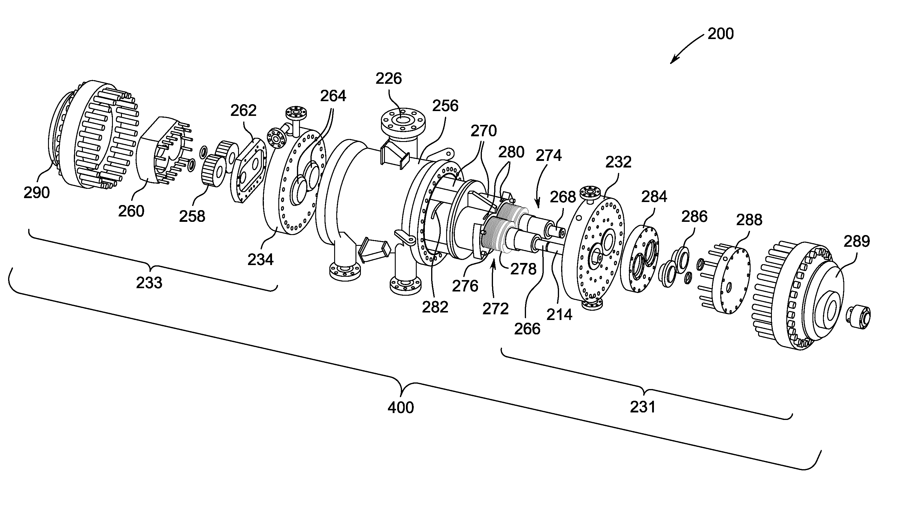
[0020]One or more specific embodiments of the present invention are described herein. In an effort to provide a concise description of these embodiments, all features of an actual implementation may not be described in the specification. It should be appreciated that in the development of any such actual implementation, as in any engineering or design project, numerous implementation-specific decisions must be made to achieve the developers' specific goals, such as compliance with system-related and business-related constraints, which may vary from one implementation to another. Moreover, it should be appreciated that such a development effort might be complex and time consuming, but would nevertheless be a routine undertaking of design, fabrication, and manufacture for those of ordinary skill having the benefit of this disclosure.

[0021]When introducing elements of various embodiments of the present invention, the articles “a,”“an,”“the,” and “said” are intended to mean that there a...


PUM

PropertyMeasurementUnit
flip angleaaaaaaaaaa
viscosityaaaaaaaaaa
back-pressureaaaaaaaaaa

Abstract

The present invention provides a pump system comprising a bearing housing coupled to a pump liner, the pump liner defining a fluid conduit, the pump liner comprising a fluid inlet and a fluid outlet; and at least one rotor having a first rotor portion and a second rotor portion, the first rotor portion being disposed within the fluid conduit and the second rotor portion being disposed within the bearing housing; the first rotor portion comprising a first conveying stage adjacent to the bearing housing, and a second conveying stage adjacent to the first conveying stage, the first and second conveying stages being configured to convey a fluid, the first conveying stage being configured to convey the fluid from the bearing housing into the fluid conduit. The new pump systems rely on a dynamic restriction to reduce the need for mechanical seals between bearing housings and raw process fluid.

Description

BACKGROUND OF THE INVENTION[0001]The embodiments disclosed herein relate generally to pumps and pump systems, and more particularly to process fluid management within pumps.[0002]Screw pumps are rotary, positive displacement pumps that may use two or more screws to transport high or low viscosity fluids or fluid mixtures along an axis. Twin-screw pumps may have two intermeshing counter-rotating screws which may at times be referred to as rotors disposed within a fluid conduit. Cavities for pumping are formed between the intermeshing screws and a pump liner or pump casing. As the screws rotate, the cavities and the fluid within the cavities are transported from an inlet to an outlet of the pump. In some applications, twin-screw pumps are used to aid in the extraction of oil and gas from on-shore and sub-sea wells. Twin-screw pumps may lower the back-pressure on a hydrocarbon reservoir and thereby enable greater total recovery from the reservoir.[0003]In conventional screw pumps, mech...

Claims


Application Information

Patent Timeline
Patent Type & Authority Applications(United States)
IPC IPC(8): F04C2/16B23P11/00
CPCF04C2/16F04C13/001F04C13/008Y10T29/49242F04C15/06F04C2240/52F04C2/084F04C15/0003
Inventor KOTHNUR, VASANTH SRINIVASAANDERSON, DAVID DELOYDGHASRIPOOR, FARSHADDEO, HRISHIKESH VISHVASDREXEL, MICHAEL V.STEEN, THOMAS LOWELL
Owner GENERAL ELECTRIC CO
Why Eureka
Try Eureka