Al technical title is built by PatSnap Al team. It summarizes the technical point description of the patent document.
A rubber needle and elastic technology, applied in the field of packaging industry, can solve the problems of inconvenient maintenance, inaccurate transfer points, complex structure, etc., and achieve the effect of convenient maintenance, prolonging life and simple maintenance.
Active Publication Date: 2019-07-12
保士特(东莞)塑胶制品有限公司
View PDF7 Cites 1 Cited by
Summary
Abstract
Description
Claims
Application Information
AI Technical Summary
This helps you quickly interpret patents by identifying the three key elements:
Problems solved by technology
Method used
Benefits of technology
Problems solved by technology
[0002] The head of the elastic rubber needle machine is the main part of the feeding of the whole machine. The feeding device of the machine head is usually a gear rotating feeding device. The material of the elastic rubber needle is usually in the shape of a ladder. There are convex points on both sides of the rubber needle. There are gears on both sides of the feeding, and the rubber needles are driven by the rotation of the gears on both sides. The main disadvantage of this feeding device is that the structure is complex. After the gears and the gears are rotated and worn, the gap becomes larger. The material transfer card point is inaccurate, and the cutting opening for the cutting material is usually fixed on the head feeding device with a blade for cutting. The wear of the blade cutting material requires frequent replacement of accessories. Complicated and not easy to maintain, for this reason, we propose an elastic glue needle nailing machine
Method used
Image
Click on the blue label to locate the original text in one second.
Reading with bidirectional positioning of images and text.
Examples
Embodiment Construction
[0020] The technical solutions in the embodiments of the present invention will be clearly and completely described below in conjunction with the accompanying drawings in the embodiments of the present invention. Obviously, the described embodiments are only a part of the embodiments of the present invention, rather than all the embodiments. Based on the embodiments of the present invention, all other embodiments obtained by those of ordinary skill in the art without creative work shall fall within the protection scope of the present invention.
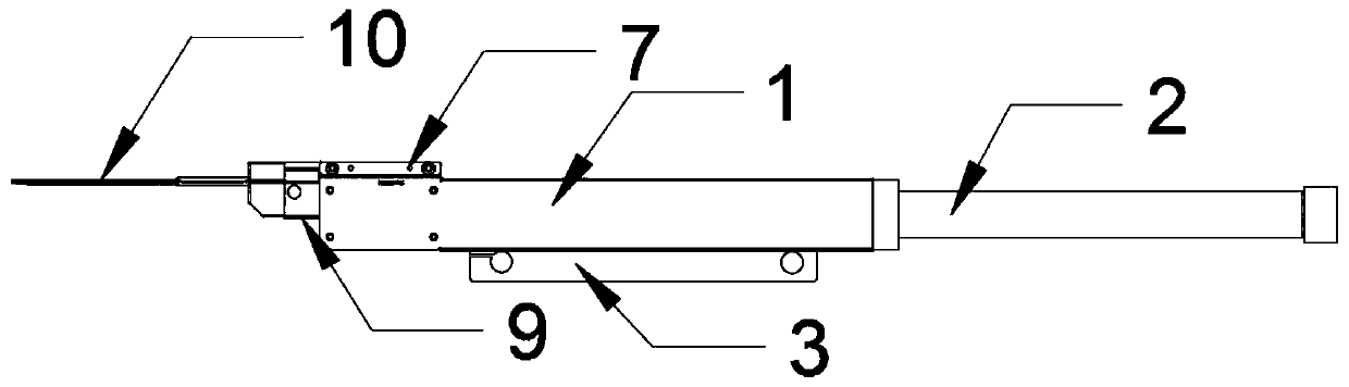
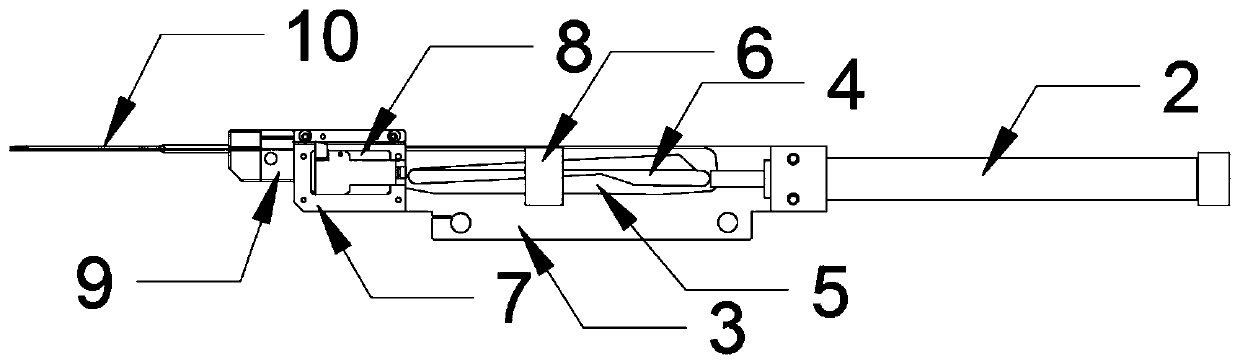
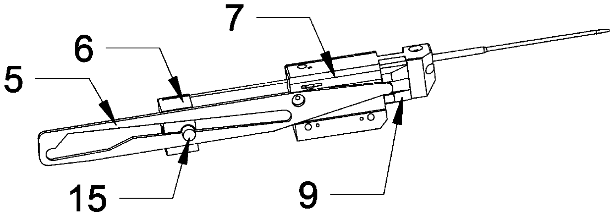
[0021] See Figure 1-6 , The present invention provides a technical solution: an elastic glue needle nailing machine, comprising a casing 1, a cylinder 2, a chute 4, a rocker 5, a moving block 6, a body 7, a feeding trough 8, a cutting block 9, and a thimble 10. , Push block 11, feed block 12, return spring 13, cutting groove 14 and sliding block 15. The cylinder 2 is installed at one end of the body 7, the surface of the body 7 is provi...
PUM
Abstract
The invention discloses an elastic staple pin nailing machine which comprises a casing, an air cylinder, a sliding chute, a rocking bar, a movable block, a machine body, a feeding groove, a cutting block, an ejection pin, a push block, a feeding block, a reset spring, a cutting groove and a sliding block, wherein the air cylinder is mounted at one end of the machine body; the sliding chute is formed in the surface of the machine body; the movable block is arranged on the surface of the sliding chute; the top surface of the movable block is in sliding fit with the sliding chute through the sliding block; the output end of the air cylinder is fixedly connected with the movable block; and the feeding groove is formed in the end, far away from the air cylinder, of the surface of the machine body. According to the elastic staple pin nailing machine, the cutting block receives the staple pin material, the rocking bar swings to enable the cutting block to move left and right so as to cut offthe staple pin material, and straight cutting of the existing cutter is changed to reduce abrasion maintenance of the cutter. The elastic staple pin nailing machine is simple in structure, easy to dismantle and mount and simple to maintain; and in addition, the feeding block pushes the staple pin material to change the existing gear driving, so that abrasion is reduced, the stability is improved,the service life is prolonged, and the elastic staple pin nailing machine can be conveniently maintained.
Description
Technical field [0001] The invention relates to the technical field of the packaging industry, in particular to an elastic glue needle nail machine. Background technique [0002] The head of the elastic glue needle machine is the main part of the whole machine. The feeding device of the machine head is usually a gear rotating feeding. The material of the elastic glue needle is usually a ladder shape with bumps on both sides of the glue needle. The needle feeding device is usually through the head There are gears on both sides of the feeding, and the glue needle is driven by the rotation of the gears on both sides. The main disadvantage of this kind of feeding device is that the structure is complicated. After the gear and the gear rotate and wear, the gap becomes larger, so that the gear is opposed to the trapezoidal glue needle. The material transfer card points are not accurate, and the cutting port of the cutting material is usually cut with a blade fixed on the head feeding d...
Claims
Application Information
Patent Timeline
Application Date:The date an application was filed.
Publication Date:The date a patent or application was officially published.
First Publication Date:The earliest publication date of a patent with the same application number.
Issue Date:Publication date of the patent grant document.
PCT Entry Date:The Entry date of PCT National Phase.
Estimated Expiry Date:The statutory expiry date of a patent right according to the Patent Law, and it is the longest term of protection that the patent right can achieve without the termination of the patent right due to other reasons(Term extension factor has been taken into account ).
Invalid Date:Actual expiry date is based on effective date or publication date of legal transaction data of invalid patent.