
Manufacturing method for elastic member

a manufacturing method and elastic member technology, applied in the field of sealing members, can solve the problems of interfacial separation, cracking, and prone to present problems, and achieve the effect of high sliding property

Active Publication Date: 2011-05-05
TOYODA GOSEI CO LTD +1
View PDF6 Cites 0 Cited by
  • Summary
  • Abstract
  • Description
  • Claims
  • Application Information

AI Technical Summary

Benefits of technology

The present invention provides a sealing member for fuel that has high sliding properties and can deform without causing separation or cracking of the sliding-treated layer from the base even when the deformation is large. The sealing member comprises a base coated with a fluororubber and a sliding-treated layer. The sliding-treated layer is formed by coating the base with a paint composition that contains a matrix of fluororubber and particulate solid lubricants. The particulate solid lubricants include a first particulate solid lubricant that can melt and a second particulate solid lubricant that is more resistant to deformation. The sealing member can be manufactured by coating the base with the paint composition and baking it. The sealing member can be used in fuel gaskets, O-rings, packings, diaphragms, valves, and other sealing members for fuel.

Problems solved by technology

The gasket 51 as shown in FIG. 9 is likely to present problems, such as interfacial separation and cracking, if its fluororubber base surface is coated with a sliding-treated layer containing a urethane resin as the matrix. FIG. 10 is an enlarged cross sectional view of a surface portion thereof.

Method used


Image

  • Manufacturing method for elastic member
  • Manufacturing method for elastic member
  • Manufacturing method for elastic member

Examples


examples

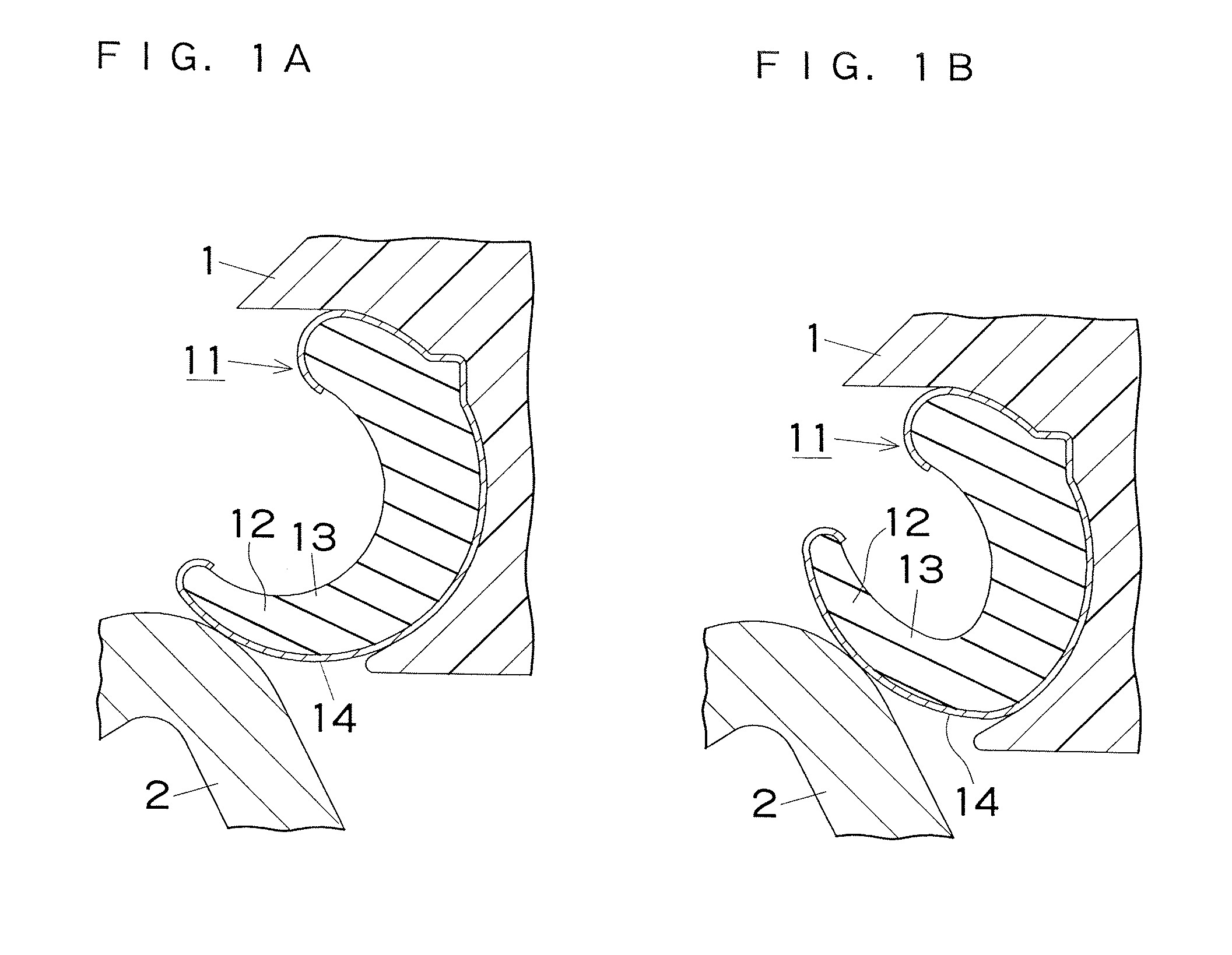
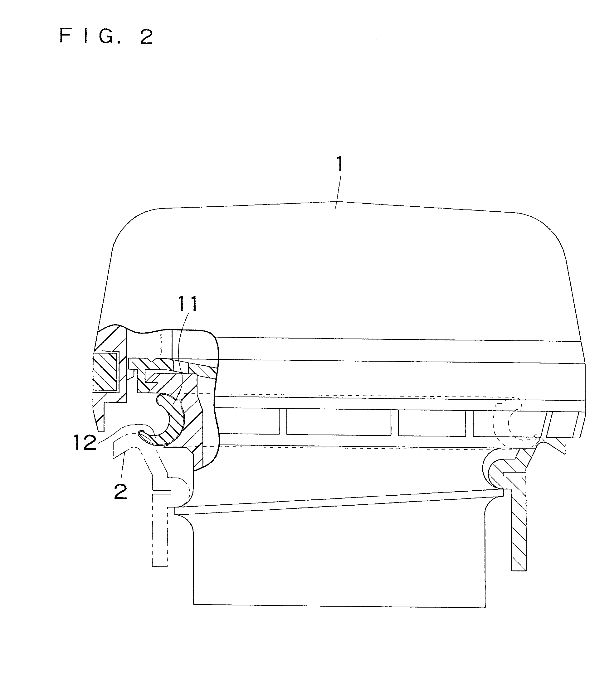
[0052]An embodiment of the present invention for gaskets for automobile fuel caps will be described below. FIGS. 1 to 6 show an example in which the present invention is embodied in a highly deformable ring having a substantially J-shaped cross section. The gasket 11 has a long lip 12 which is deformable in use to as large an extent as, for example, 4.5 mm when pressed against a filler neck 2.

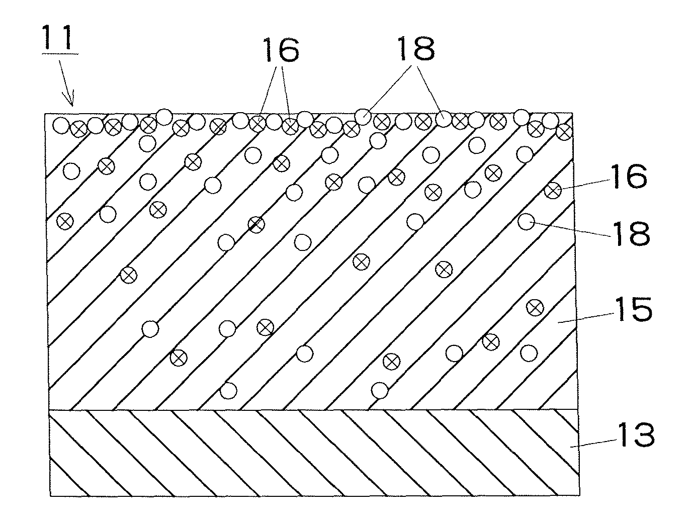
[0053]The gasket 11 comprises a fluororubber base 13 and a sliding-treated layer 14 having a thickness of about 12 μm and covering the surface of the base 13 from its portion contacting a fuel cap 1 to its portion terminating in the outer edge of the lip 12. As shown in FIG. 3B, the sliding-treated layer 14 contains a matrix made from a fluororubber 15, a sliding thin film 17 formed in the surface portion of the matrix 15 from a molten first particulate solid lubricant 16 and a second particulate solid lubricant 18 dispersed in the matrix 15 and the sliding thin film 17 without being melted. Th...


PUM

PropertyMeasurementUnit
particle diameteraaaaaaaaaa
elongationaaaaaaaaaa
particle diameteraaaaaaaaaa

Abstract

The present invention provides a sealing member for fuel which includes a fluororubber base and a sliding-treated layer coating the surface of the base. The sliding-treated layer includes a matrix made from a fluororubber, a sliding thin film formed in the surface portion of the matrix from a molten first particulate solid lubricant, and a second particulate solid lubricant dispersed in the matrix and the sliding thin film without being melted.

Description

CROSS-REFERENCE TO RELATED APPLICATIONS AND INCORPORATION BY REFERENCE[0001]The present application is a divisional of U.S. patent application Ser. No. 11 / 589,288 filed on Oct. 30, 2006, which claims priority under 35 U.S.C. §119 to Japanese Patent Application Nos. 2005-317068 filed on Oct. 31, 2005 and 2005-380604 filed on Dec. 29, 2005. The contents of these prior applications are incorporated herein by reference in their entireties.TECHNICAL FIELD[0002]The present invention relates to sealing members for fuel, such as gaskets (particularly for fuel caps), O-rings, packings, diaphragms and valves, which are likely to contact fuel, and paint compositions for those members.BACKGROUND OF THE INVENTION[0003]Gaskets for fuel caps have recently come to be formed from fluororubbers having high gasoline permeation resistance to comply with the requirement for fuel permeation control (Japanese Patent Application Publication No. JP-A-2004-60819). The gasket for a fuel cap has a fluororubber...

Claims


Application Information

Patent Timeline
Patent Type & Authority Applications(United States)
IPC IPC(8): B05D3/02
CPCC08L27/12C08L27/18C08L2205/03C09D127/12F16J15/102F16J15/022C08L2666/04
Inventor HAGANO, HIROYUKIINOUE, SHINICHIROTANGIKU, KOICHI
Owner TOYODA GOSEI CO LTD
Learn More