
Bridge inspection robot capable of climbing obstacle

a technology of a bridge and an inspection robot, which is applied in the direction of bridges, instruments, program control, etc., can solve the problems of high cost of visually inspecting cracks or corrosions of bridges, inability to ensure the safety of a worker or a worker, and inability to perform inspection work reliably

Inactive Publication Date: 2011-05-05
EXPRESSWAY & TRANSPORTATION RES INST KOREA EXPRESSWAY CORP
View PDF6 Cites 36 Cited by
  • Summary
  • Abstract
  • Description
  • Claims
  • Application Information

AI Technical Summary

Benefits of technology

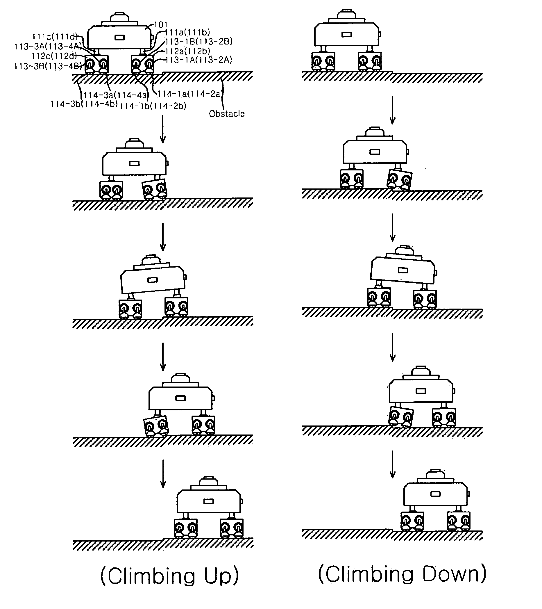
[0023]Therefore, the present invention provides a bridge inspection robot which climbs up / down an obstacle which exists in a bridge inspection path, and which adjusts a photographing angle of a camera so as to correspond to a slope of the robot through a slope detection sensor and a camera angle adjustment portion, when the robot climbs over the obstacle, to thereby maintain the photographing angle to be perpendicular between the camera and the lower surface of the bridge all the time although the slope of the robot is changed.
[0024]In addition, a body tube of the camera is escalated so as to correspond to a photographing height change of the camera, through an altitude detection sensor and a camera height adjustment portion when the robot climbs up / down an obstacle, to thereby maintain an identical photographing height all the time although a photographing height of the camera is changed with respect to the lower surface of the bridge when the robot climbs over the obstacle.
[0025]In addition, the bridge inspection robot avoids and climbs over an obstacle such as a vertical stiffener which is provided vertical with the upper side of the flanges, respectively, when the robot moves along a bridge inspection path, for example, the flanges, without having caused position changes of the robot, to thereby enable the camera to continuously photograph the lower surface of the bridge.

Problems solved by technology

However, it costs very high to visually inspection cracks or corrosions of abridge as described above, since a workbench or a moving path such as a scaffold should be installed.
Moreover, when much wind blows, the workbench or the moving path sways, and thus there is a disadvantage safety of a worker or workers cannot be ensured.
In addition, when a bridge inspection work is visually performed, only a worker can see data of corrosions or cracks of a bridge.
Accordingly, an inspection work is not reliable, and the data cannot be stored.
As a result, there is a problem that a review or analysis of the inspection data becomes difficult later.
However, when the above-described mobile robot is used to move on a flange between a girder and another girder of aPSC box bridge in order to inspect the lower surface of the bridge, or to inspect the inner portion of the box of a SBG bridge, there has occurred a problem that the mobile robot cannot continuously move because of obstacles such as partitions, bridge joint members or vertical stiffeners which are provided in a box.
Accordingly, when the mobile robot avoids the obstacles and moves, there has occurred a problem that a position of the bottom surface of the bridge is changed, and the bottom surface of the bridge cannot be successively photographed.
In addition, since images photographed according to position changes of the mobile robot have respectively different position information (for example, coordinates that correspond to in an altitude or distance from a camera), there are problems that a lot of errors occur in processing continuous images in correspondence to a photographing position, and accordingly reliability regarding an image analysis is lowered in the case that a defect analysis regarding a bridge is carried out.

Method used


Image

  • Bridge inspection robot capable of climbing obstacle
  • Bridge inspection robot capable of climbing obstacle
  • Bridge inspection robot capable of climbing obstacle

Examples


Embodiment Construction

[0036]The above and / or other objects and / or advantages of the present invention will become more apparent by the following description.

[0037]Hereinafter, a bridge inspection robot according to a preferred embodiment of the present invention will be described with reference to the accompanying drawings in detail.

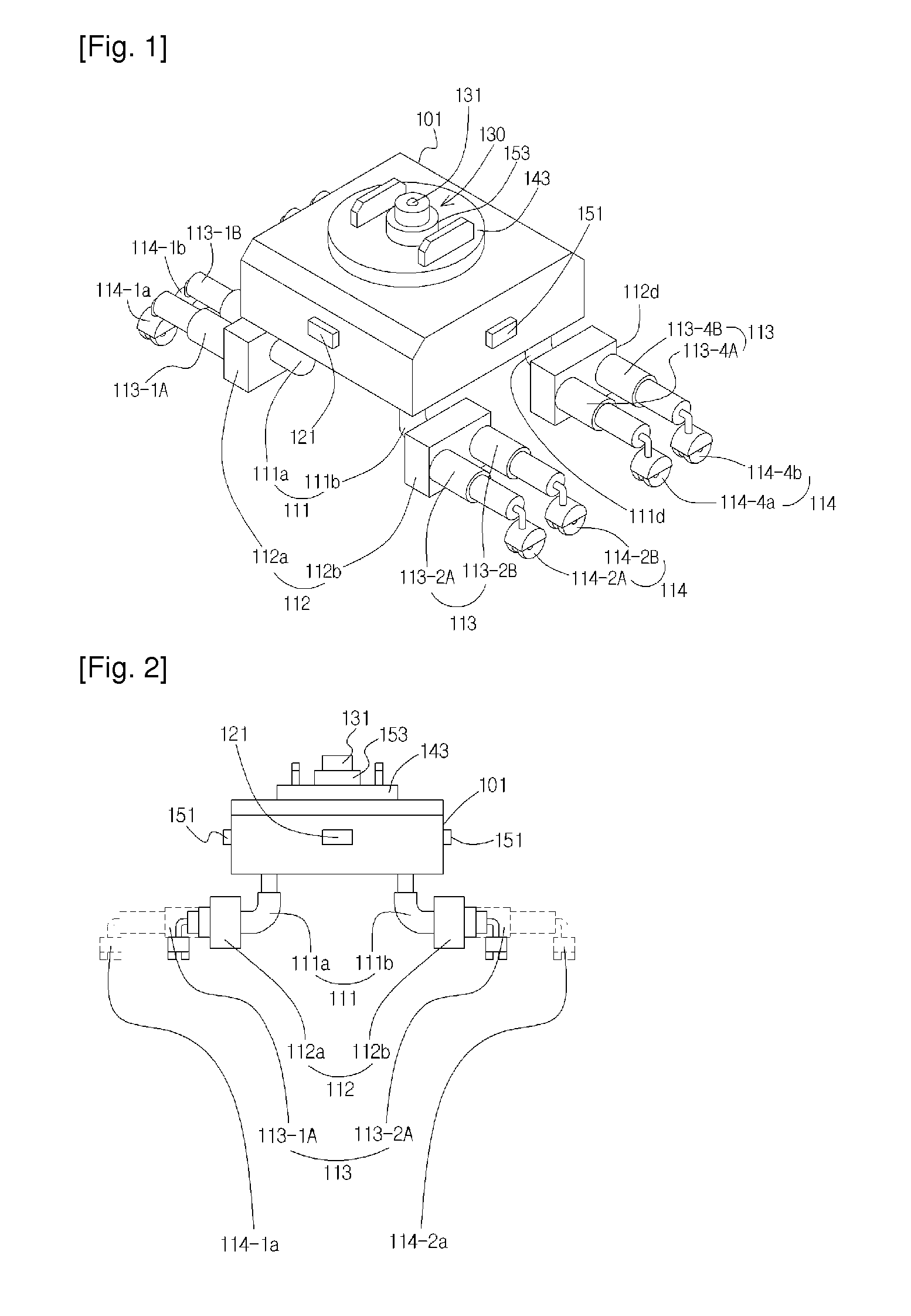
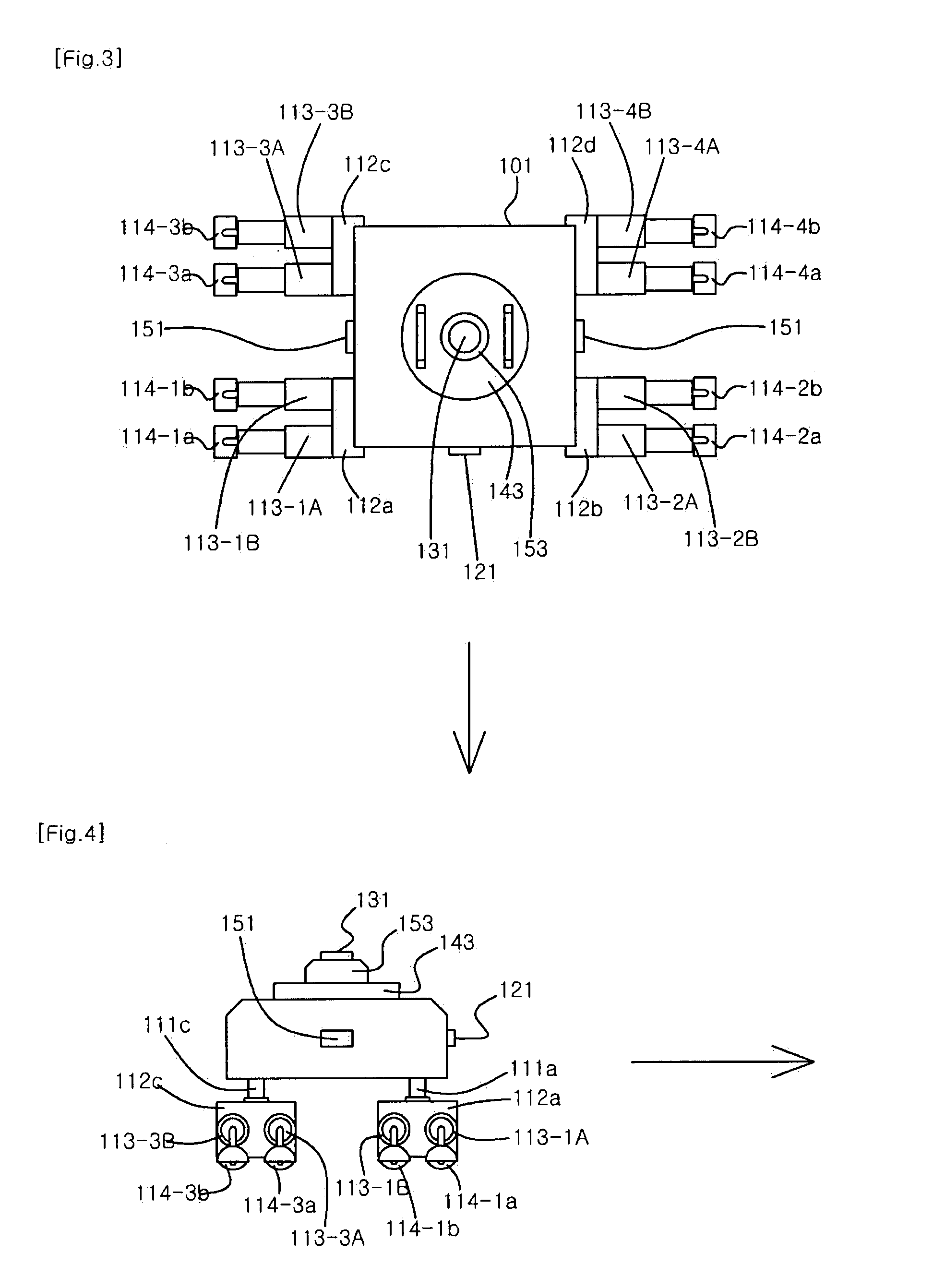
[0038]FIG. 1 is a perspective view showing a robot for inspecting a bridge which is capable of climbing over an obstacle according to a preferred embodiment of the present invention. FIGS. 2 to 4 are a front view, a plan view and a side view showing the bridge inspection robot of FIG. 1, respectively. FIG. 5 block diagram schematically showing the bridge inspection robot of FIG. 1. FIGS. 6 and 7 show a use state of the bridge inspection robot of FIG. 1, respectively.

[0039]As shown in FIGS. 1 through 7, a bridge inspection robot which is capable of climbing over an obstacle, according to a preferred embodiment of the present invention, includes: a climbing-over portion 110 whi...


PUM


Abstract

Provided is a bridge inspection robot which is capable of climbing over an obstacle, the bridge inspection robot including: a climbing-over portion (110) which is extended to correspond to a gap distance between a flange (1 Ia) of a first girder (11) and a flange (12a) of a first girder (12) which are provided at the upper side of a pier (L) of a bridge (10) in which a robot main body (101) climbs up / down or avoids and climbs over an obstacle, when the robot main body (101) moves on the flange, for example, along a bridge inspection path; an obstacle detection portion (120) which detects the obstacle which exists on the flanges; a photographing altitude control portion (150) which detects an altitude change of an image photographing portion (130) according to height of the obstacle when the robot main body (101) climbs up / down or avoids and climbs over the obstacle, and adjusts a photographing height of the image photographing portion (130) so as to correspond to the altitude change, to thus have a z-axis coordinate of an identical height all the time; a position calculation portion (160) which measures a mobile position of the robot main body (101) which corresponds to a consecutive image

Description

TECHNICAL FIELD[0001]The present invention relates to a robot for inspecting a bridge, and more particularly to, a bridge inspection robot which is capable of climbing over an obstacle so as to successively photograph the bottom surface of a bridge in which the bridge inspection robot climbs up / down or avoids and climbs over an obstacle such as a vertical stiffener which is provided vertically with a prestressed concrete (PSC) box splice connection portion or a flange, when the bridge inspection robot moves along a bridge inspection path for a PSC box bridge or a stability of bridge girders (SBG) bridge, for example, on a flange between a girder and another girder.BACKGROUND ART[0002]Generally, a PSC box bridge or a SBG bridge is a representative type of a long and large bridge whose span is long. In the case of inspecting whether or not there are cracks or corrosions on a lower surface of a bridge between a girder and another girder, a workbench or a moving path such as a scaffold ...

Claims


Application Information

Patent Timeline
IPC IPC(8): B25J13/08B25J19/04B62D51/00
CPCG03B2205/0007B25J5/007G03B2205/00B25J19/021E01D19/16E01D19/106G02B27/648B25J5/00E01D19/10
Inventor LEE, BYEONG-JUSHIN, JAE-INPARK, CHANG-HOPARK, YOUNG-HONAM, MOON-SEOK
Owner EXPRESSWAY & TRANSPORTATION RES INST KOREA EXPRESSWAY CORP
Learn More