
Method and apparatus for starting an engine in a hybrid vehicle

a hybrid vehicle and engine technology, applied in the direction of capacitor propulsion, battery/fuel cell control arrangement, electric devices, etc., can solve the problems of unsatisfactory acceleration changes, and achieve the effect of increasing torque and maintaining the acceleration of the vehicl

Active Publication Date: 2013-03-05
GE HYBRID TECH
View PDF30 Cites 23 Cited by
  • Summary
  • Abstract
  • Description
  • Claims
  • Application Information

AI Technical Summary

Benefits of technology

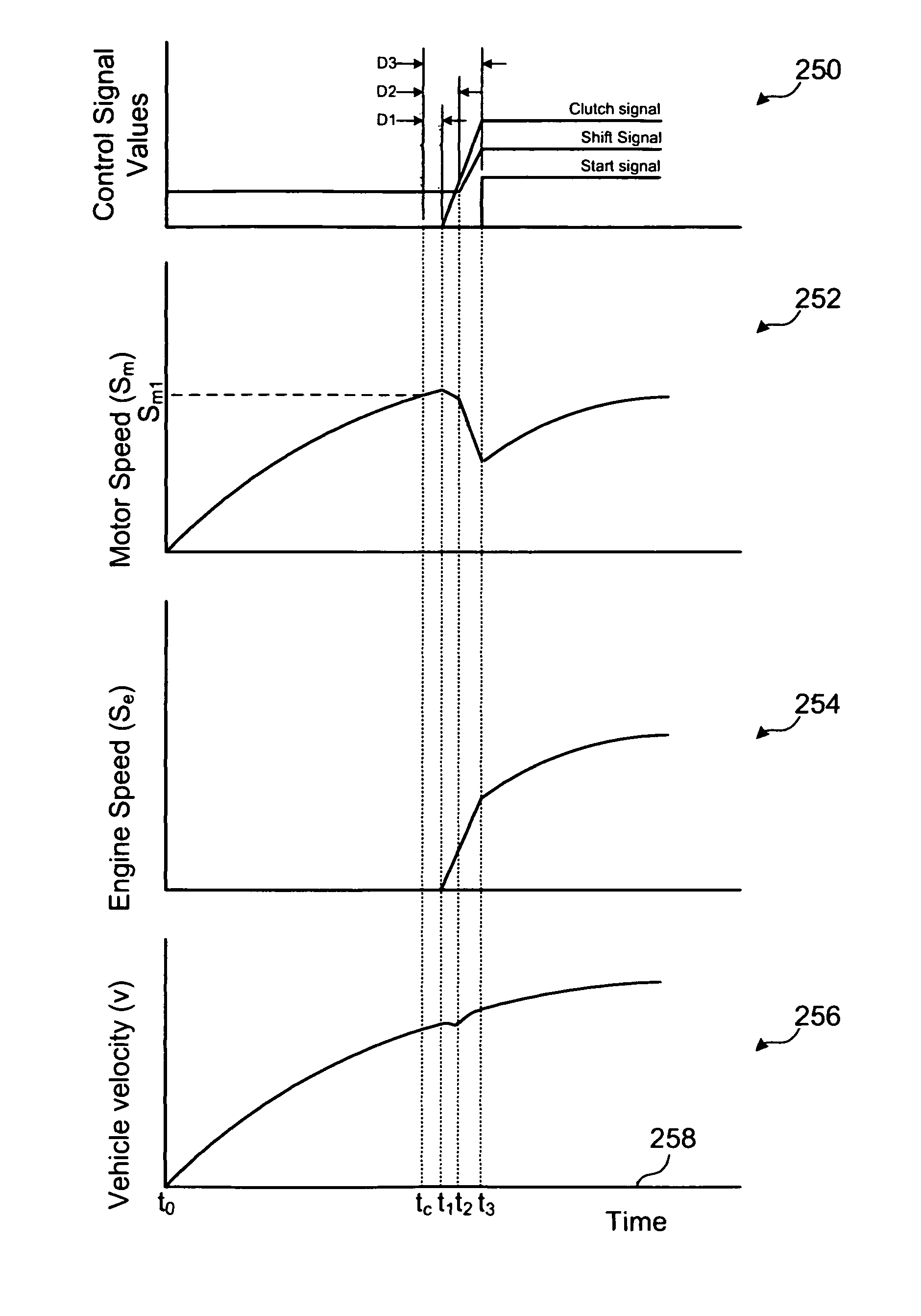
The invention provides a method and apparatus for starting an engine in a hybrid vehicle that is driven by an electric motor. This allows for a smooth and effective transition from electric to gas power during acceleration, while maintaining the vehicle's speed. The method involves quickly coupling the engine to the motor and then reducing the speed of the motor to provide the starting torque to the engine. The automatic transmission gear ratio is then adjusted to match the reduced motor speed, allowing for a smooth transition and increased torque delivery. Overall, this technology allows for a seamless and efficient start-up of hybrid vehicles.

Problems solved by technology

The diversion of torque from the vehicle wheels to the engine while starting the engine may result in undesirable acceleration changes.

Method used


Image

  • Method and apparatus for starting an engine in a hybrid vehicle
  • Method and apparatus for starting an engine in a hybrid vehicle
  • Method and apparatus for starting an engine in a hybrid vehicle

Examples


first embodiment

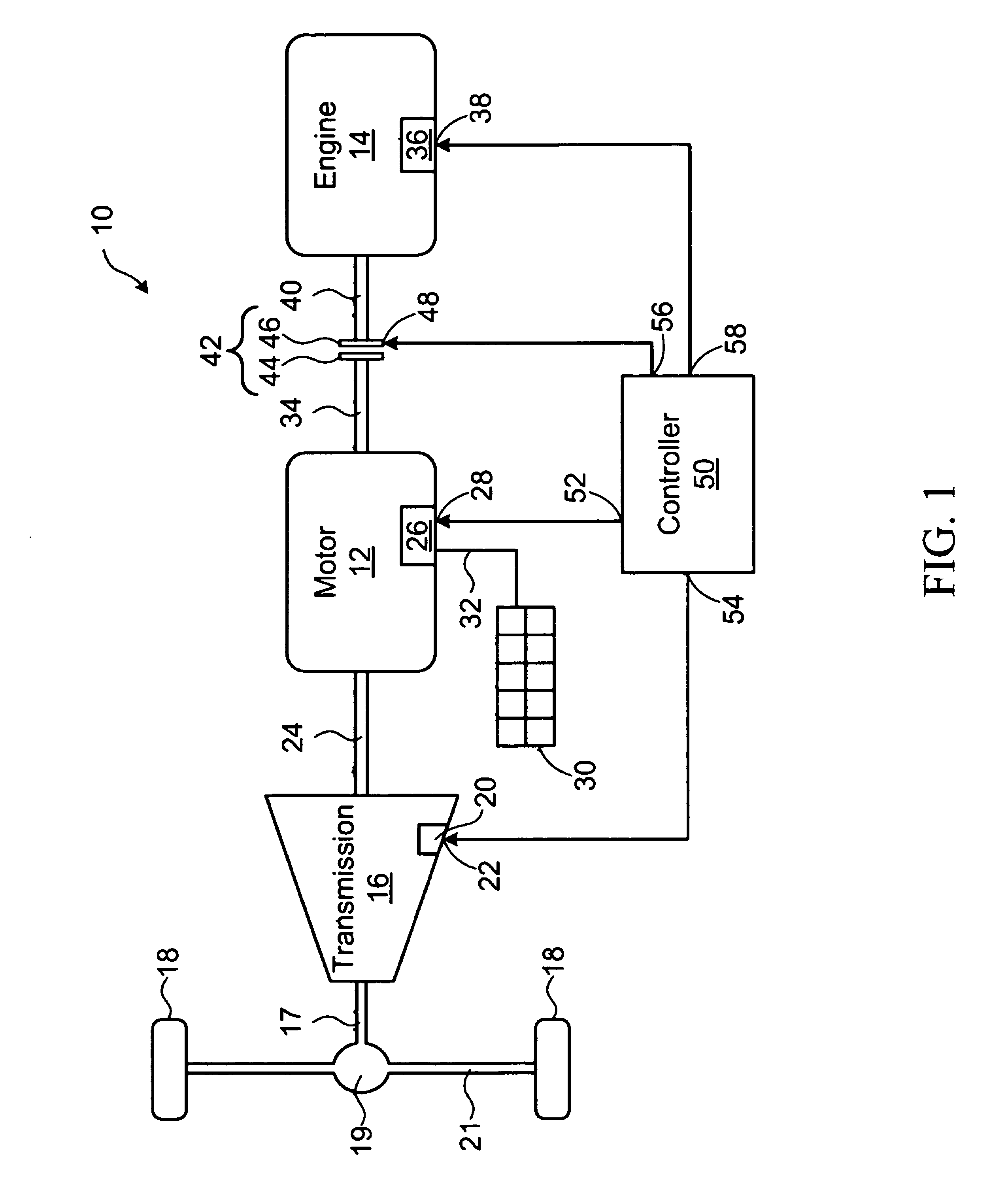
[0060]Referring to FIG. 1, a hybrid vehicle according to the invention is shown generally at 10. The hybrid vehicle 10 includes an electric motor 12, an engine 14, an automatic transmission 16, and a pair of drive wheels 18.

[0061]The automatic transmission 16 is mechanically coupled to the drive wheels 18 through a transmission output shaft 17, a differential 19, and a drive axle 21. The automatic transmission 16 includes an interface 20 having an input 22 for receiving a shift signal for causing the automatic transmission to change gear ratio. The automatic transmission 16 may comprise a conventional automatic transmission having a plurality of gears (not shown), which may be configured to provide a plurality of discrete gear ratios between the first shaft 24 and the transmission output shaft 17. Alternatively, the automatic transmission 16 may include a continuously variable transmission that is responsive the shift signal to provide gear ratios within a range of gear ratios that ...

second embodiment

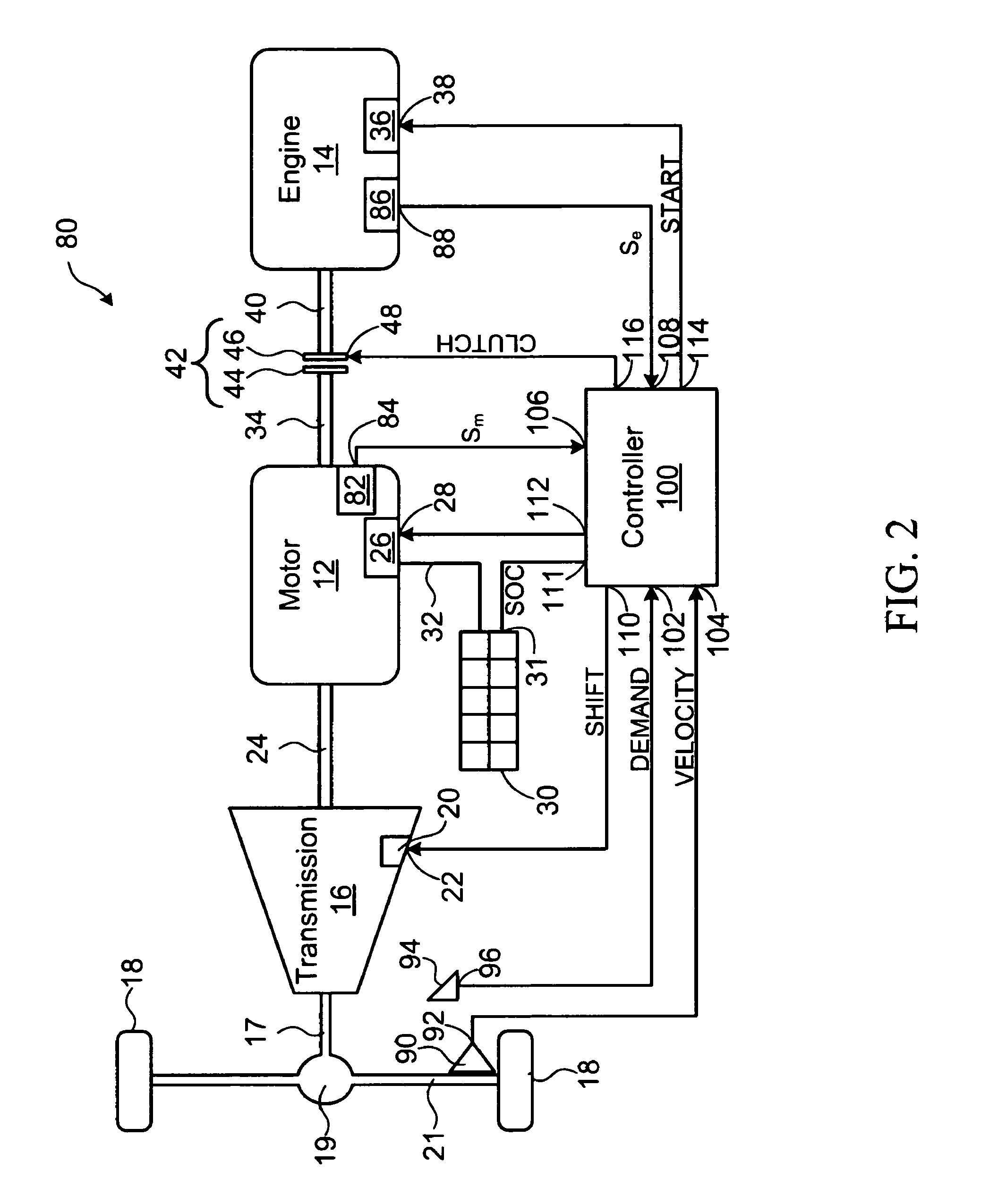
[0076]Referring to FIG. 2, a hybrid vehicle is shown generally at 80. The hybrid vehicle 80 includes the motor 12, the engine 14, the automatic transmission 16, and the energy storage element 30, generally as shown in FIG. 1.

[0077]The motor 12, in this embodiment, further includes a speed sensor 82 having an output 84 for producing a motor speed signal (Sm) representing a rotational speed of the motor.

[0078]The engine 14 further includes a speed sensor 86 having an output 88 for producing an engine speed signal (Se) representing a rotational speed of the engine.

[0079]The hybrid vehicle 80 further includes a velocity sensor 90 having an output 92 for producing a vehicle velocity signal representing a velocity of the vehicle. In general the velocity sensor 90 may be mechanically, optically, or magnetically coupled to the axle 21 or one of the drive wheels 18 and the velocity sensor 90 may further include circuitry for converting a sensed rotational speed of the wheels 18 or axle 21 in...


PUM


Abstract

A method and apparatus for starting an engine in a hybrid vehicle being driven by an electric motor is disclosed. The motor is operably configured to deliver mechanical power through an automatic transmission to at least one vehicle drive wheel to cause an acceleration of the vehicle. The method involves coupling the engine to the motor to cause an inertial load on the motor thus causing the motor to decelerate to a reduced rotational speed to provide a starting torque to the engine for starting the engine, and causing the automatic transmission to change gear ratio to a target gear ratio associated with the reduced rotational speed while causing the motor to decelerate, the motor being operable to deliver increased torque at the reduced rotational speed, thereby generally maintaining the acceleration of the vehicle.

Description

BACKGROUND OF THE INVENTION[0001]1. Field of Invention[0002]This invention relates generally to hybrid vehicles and more particularly to starting an engine in a hybrid vehicle.[0003]2. Description of Related Art[0004]Hybrid electric vehicles having an engine (such as an internal combustion engine) and an electric motor, for providing power to the vehicle have become a viable alternative to conventional internal combustion engine vehicles. While such vehicles may require more complex power transmission components, this complexity is offset by improved fuel consumption and a corresponding reduction in pollutant emissions from the engine.[0005]Given the present climate of higher prices for fossil fuels, there is a corresponding desire to further reduce fuel consumption costs when operating hybrid vehicles. Hybrid electrical vehicles reduce fuel consumption by apportioning the power required to operate the vehicle between the engine and electric motor, to cause these components to opera...

Claims


Application Information

Patent Timeline
Patent Type & Authority Patents(United States)
IPC IPC(8): B60W20/00B60W10/06B60W10/00B60K1/00
CPCB60K6/48B60W10/02B60W10/06B60W10/08B60W10/115B60W20/00B60W30/192B60K6/46B60L11/005B60L11/14B60L11/1861B60L11/1864B60L15/2054B60K6/547Y10T477/641B60W2510/0695B60W2710/025Y02T10/6221Y02T10/6286B60Y2300/50B60L2200/12B60L2210/40B60L2220/12B60L2220/16B60L2240/12B60L2240/421B60L2240/423B60L2240/441B60L2240/443B60L2240/486B60L2240/507B60L2240/80B60L2260/26B60L2270/145Y10T477/656Y10T477/23Y02T10/70B60L50/40B60L50/16B60L58/12B60L58/21Y10S903/918Y10S903/919Y10S903/93Y02T10/64Y02T10/7072Y02T10/72B60K2006/268B60W10/10B60W20/30Y02T10/62B60K6/543B60W10/101B60W10/11B60W20/10B60W2510/081B60W2510/244B60W2520/10B60W2710/021B60W2710/081B60W2710/1005B60W2720/10B60Y2200/92B60Y2300/192B60Y2300/42B60Y2300/43B60Y2300/60B60Y2400/70B60Y2400/72
Inventor BOUCHON, NICOLAS LOUIS
Owner GE HYBRID TECH
Learn More