

Non-pneumatic tire
- Summary
- Abstract
- Description
- Claims
- Application Information
AI Technical Summary
Benefits of technology
Problems solved by technology
Method used
Image

Examples
first embodiment
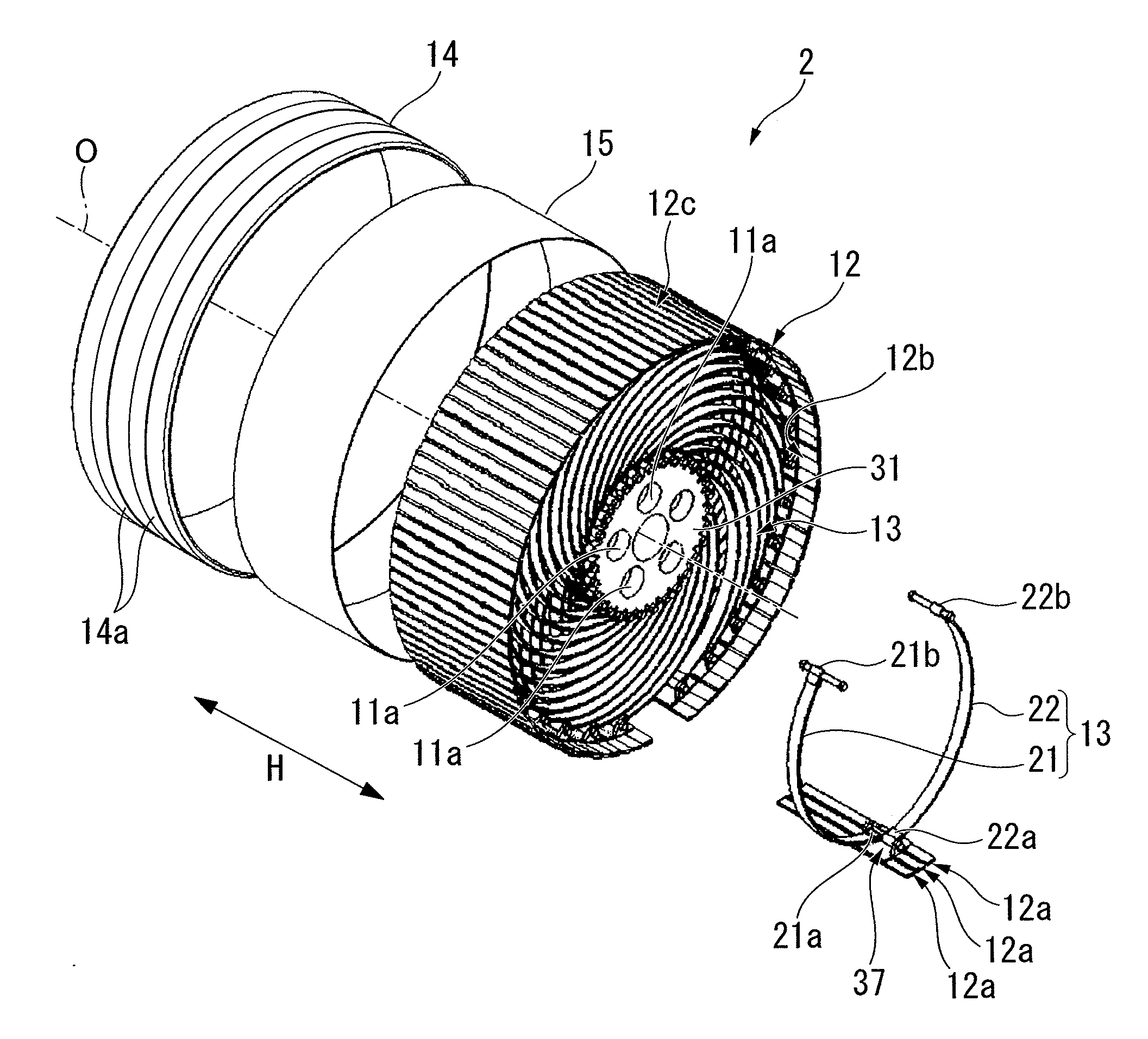
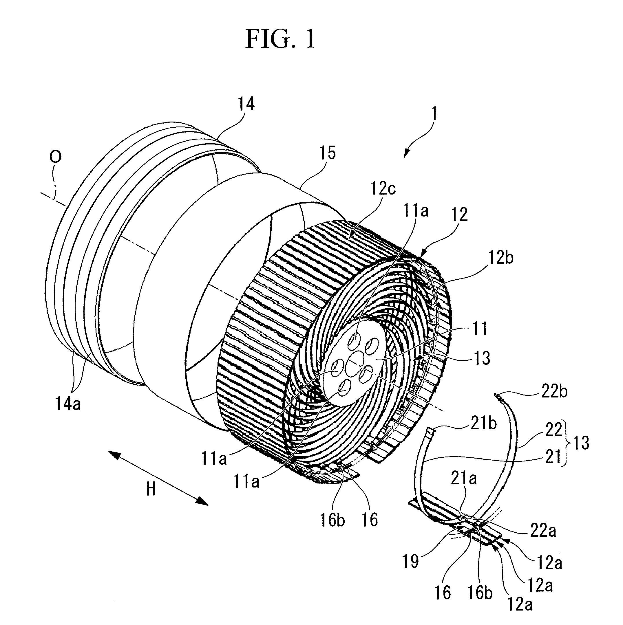
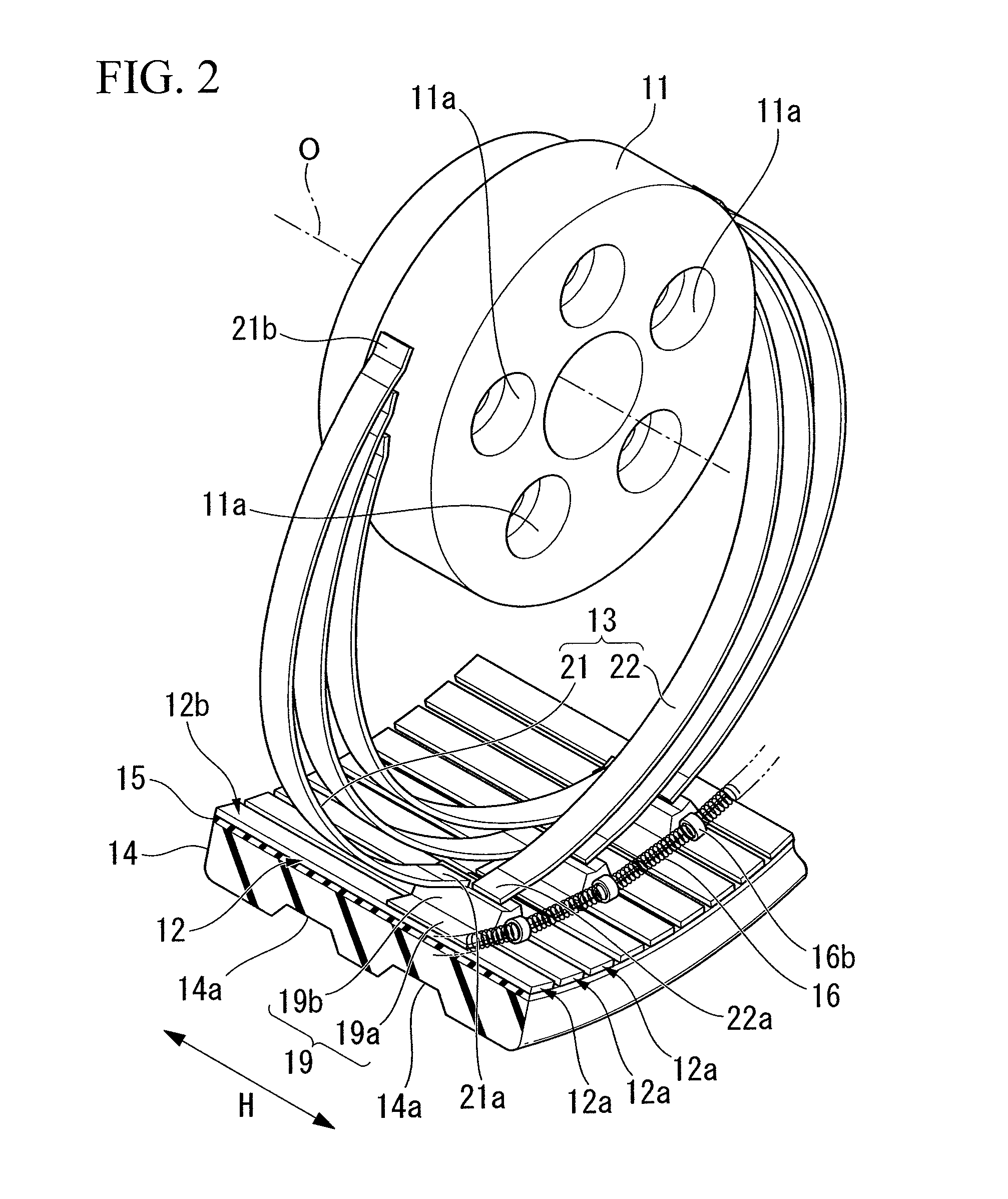
a non-pneumatic tire according to the present invention will be described hereafter making reference from FIG. 1 to FIG. 3B.
The non-pneumatic tire 1 is provided with an mounting body 11 mounted on an axle (not shown), an annular body 12 encircling the mounting body 11 from the outside in the tire-radial direction, a plurality of connecting members 13 that is disposed along the tire-circumferential direction and connects the outer circumferential face of the mounting body 11 and the inner circumferential face 12b of the annular body 12, a tread member 14 disposed over the entire outer circumferential face 12c of the annular body 12, and a reinforcing layer 15 disposed between the annular body 12 and the tread member 14.
The mounting body 11 has a circular shape in a side view of the non-pneumatic tire 1 from a direction of an axial line O, and a plurality of mounting holes 11a is formed at the radial center in the mounting body 11. For example, bolts are inserted into these mounting h...
PUM
 Abstract
Description
Claims
Application Information