Drive hand-control system for a lawn mower

a technology of hand control and lawn mower, which is applied in the direction of mechanical control devices, instruments, agriculture tools and machines, etc., can solve the problems of many control members, difficult for the operator to keep in mind, and the operator's effort to keep the drive engaged, etc., to achieve simple and reliable solution, more allowance, and the effect of increasing the number of controls

Inactive Publication Date: 2011-05-12
HUSQVARNA AB
View PDF5 Cites 15 Cited by
  • Summary
  • Abstract
  • Description
  • Claims
  • Application Information

AI Technical Summary

Benefits of technology

[0017]Also, an advantage of the present invention is that the number of controls that the operator needs to keep track of during the mowing is limited, since there is only one control (the OPC) that needs to be continuously engaged by the operator.
[0018]The drive engagement control may further comprise a movable lever having the two stable positions as end positions distant from each other. The two end positions of the lever may be provided in the form of an over-centre mechanism, in which the lever can be moved from any one of its stable end positions towards an over-centre position, against a force exerted by the over-centre mechanism, and further from the over-centre position towards the other of its stable end positions, supported by a force exerted by the over-centre mechanism.
[0019]The over-centre mechanism is a simple and reliable solution for obtaining the desired function with stable positions. When the operator changes the position of the lever from “on” to “off” or vice versa, the over-centre mechanism gives a clear indication that the intended position (“on” or “off”) is achieved. Also, the construction of an over-centre mechanism has much more allowance than for example a solution based on friction, where more accuracy is required.
[0020]The drive engagement control may be mounted at the handle arrangement in the vicinity of a handle portion where the operator is intended to hold his or her hands.
[0021]This placement of the drive engagement control makes it easy to use the system and the operator does not lose his or her focus on the manoeuvring of the mower when operating the control. Thereby it contributes to a safe driving of the mower.
[0022]Further, the drive engagement control may be connected to the OPC in such a way that the drive engagement control is set in its disengaging position when the operator releases the OPC into its disengaged position and that the drive engagement control can be set in its engaging position only if the OPC is in its engaged position. Thereby, the operator only needs to release the OPC in order to quickly stop the mower from driving forward. Also, it is ensured that the drive is not unintentionally engaged, when the mower is started again.

Problems solved by technology

The drive hand-control systems of the mowers now available on the market all have the disadvantage that it takes some effort from the operator to keep the drive in its engaged position.
Also, a disadvantage with some of them is that there are many control members to keep track of during the operation of the mower.
In the case where two “bail arms” are provided for different purposes it may be hard for the operator to keep in mind which one is used for engaging the drive and which one is used for enabling the power unit to run.
However, such a speed control implies a continuous strain on the hand of the operator and prevents the operator from moving his or her hands in order to get a more comfortable grip.
However, this kind of speed control as well implies a continuous strain on one or both of the operator's hands, and therefore does not provide an ergonomic solution.
However, to engage the drive the operator must grasp and press a second “bail arm”, and therefore this drive hand-control system is not an ergonomically advantageous solution.

Method used


Image

  • Drive hand-control system for a lawn mower
  • Drive hand-control system for a lawn mower
  • Drive hand-control system for a lawn mower

Examples


Embodiment Construction

[0037]An embodiment of the invention will be described below with reference to the FIGS. 1-8.

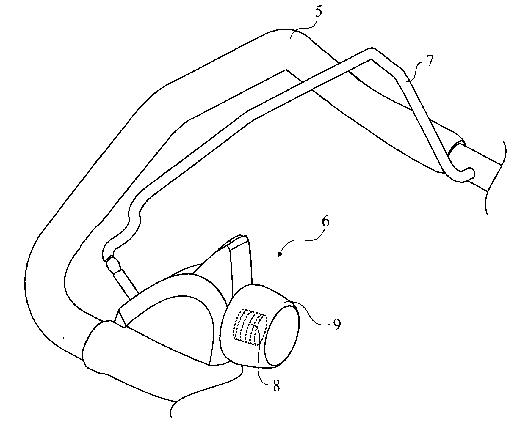
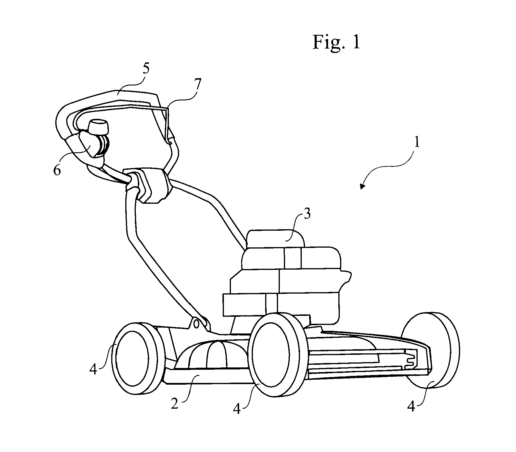
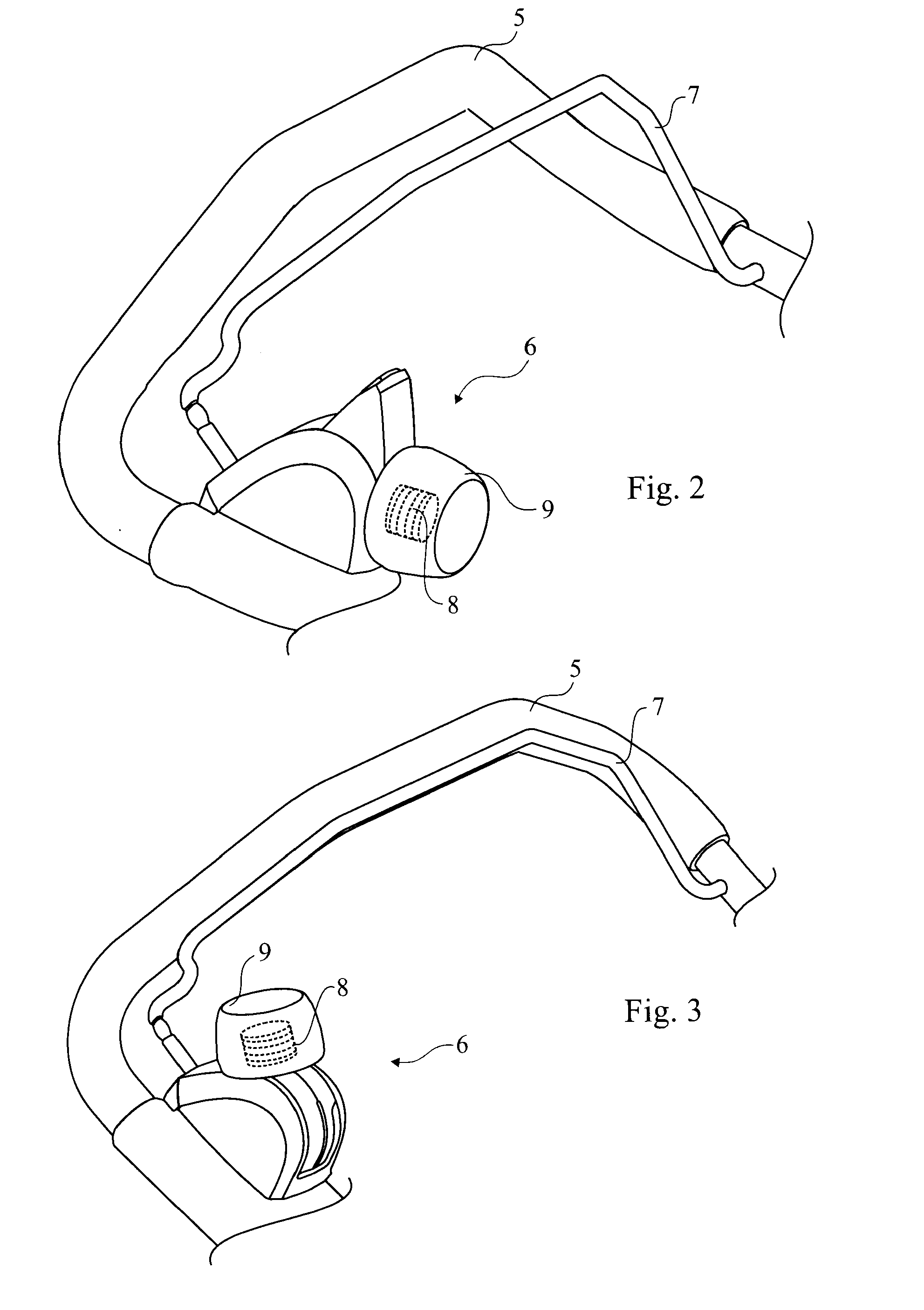
[0038]FIG. 1 shows a lawn mower 1 comprising a mower deck 2, a power unit 3, wheels 4, a handle arrangement 5, hereinafter the handle, for guidance of the lawn mower by an operator, a drive hand-control system 6 and an OPC (operator presence control) 7. The power unit 3 is arranged to generate drive force to one or more propulsion members via a drive arrangement (FIG. 5-6), and to a cutting member (not shown). The propulsion member or members can be any one or more of the wheels 4 in the illustrated embodiment, although typically the two rearmost wheels serve as driving wheels. The handle 5 extends upwardly and rearwardly from the rear portion of the mower deck 2. At the rear part of the handle 5 and in close vicinity of the hands of the operator the drive hand-control system 6 and the OPC 7 are arranged for the manipulation by the operator.

[0039]In an alternative solution the mower 1 may co...


PUM


Abstract

A drive hand-control system (6) mainly located at a lawn mower handle arrangement (5) intended for guidance of the lawn mower by an operator, the lawn mower having at least one power unit for driving at least one propulsion member and a cutting member, a drive arrangement for transmitting drive force to the at least one propulsion member and an operator presence control (7) located at the lawn mower handle arrangement (5) preferably for hand engagement by the operator, the drive hand-control system (6) comprising a drive engagement control (8) having at least two positions, where a first position disengages the drive of the at least one propulsion member and a second position engages the drive of the at least one propulsion member, and the drive engagement control (8) being switchable between the at least two positions by the operator, and the first position and the second position of the drive engagement control (8) being stable positions, which are stable without any effort from the operator, except for the effort possibly required for the hand engagement of the operator presence control (7).

Description

TECHNICAL FIELD[0001]This invention relates to a drive hand-control system for a lawn mower, especially for a self-propelled lawn mower of the walk-behind type.BACKGROUND[0002]Self-propelled walk-behind lawn mowers, where a power unit is used for the propulsion of the mower, are provided with a drive hand-control system of some kind. Such a system comprises means for engaging and disengaging the drive mechanism of the mower. Also, it often comprises means for adjusting the speed of the mower.[0003]The drive engagement means as well as the speed adjustment means comprise control members, which may be provided at the rear part of the lawn mower handle together with other controls for operation of the user, such as the operator presence control (OPC), or so-called dead man control. The OPC is provided for safety reasons and ensures that the cutting element rapidly stops running if the operator loses control over the mower. The OPC is normally provided as an elongated handle, “bail arm”...

Claims


Application Information

Patent Timeline
Patent Type & Authority Applications(United States)
IPC IPC(8): G05G1/04
CPCA01D2034/6843A01D34/824
Inventor LEVANDER, ANDREASFORSBERG, HELENAJOHANSSON, JORGEN
Owner HUSQVARNA AB
Why Eureka
Try Eureka