
Key switch structure

a key switch and switch technology, applied in the direction of adhesives, contact mechanisms, electrical appliances, etc., can solve the problems of insufficient glue between the two, difficult to form a waterproof sheet in such a particular form, and the waterproof sheet thus formed is likely to be so thick, so as to improve the waterproofing property of the membrane sheet

Inactive Publication Date: 2011-05-12
OKI ELECTRIC IND CO LTD
View PDF11 Cites 31 Cited by
  • Summary
  • Abstract
  • Description
  • Claims
  • Application Information

AI Technical Summary

Benefits of technology

[0007]In view of overcoming the above-described problems in the prior art, it is an object of the present invention to provide a key switch structure excellent in waterproofing property and a method of manufacturing such a key switch structure.
[0009]According to the present invention, it is possible to enhance the waterproofing property of the membrane sheet without affecting operation of the key switch so as to prevent liquid, whenever spilt on the keyboard, from getting into the membrane sheet layers.
[0010]Further, there is no need to form a waterproof sheet in a particular form, so that it is possible to make the waterproof sheet thinner.
[0011]Furthermore, according to the present invention, there is no need to glue a plurality of membrane sheet layers to each other, and thus it is possible to overcome the difficulty in establishing a sufficient gluing area of the membrane sheet.

Problems solved by technology

The layers 220, 222 and 224 cannot provide sufficient area for gluing them due to reduction in thickness and size of the keyboard, and thus, they are not sufficiently glued to each other.
However, in the case of thin or small-sized keyboard, it is difficult to form a waterproof sheet in such a particular form, i.e. to form a resin film or other materials to provide a waterproof wall for each key.
Moreover, a waterproof sheet thus formed is likely to be made so thick that the operator receives a repulsive force of the sheet when he or she depresses the key switch.
Therefore, it takes time since the operator starts depressing the key top until the contact of the key switch is closed.

Method used


Image

  • Key switch structure
  • Key switch structure
  • Key switch structure

Examples


Embodiment Construction

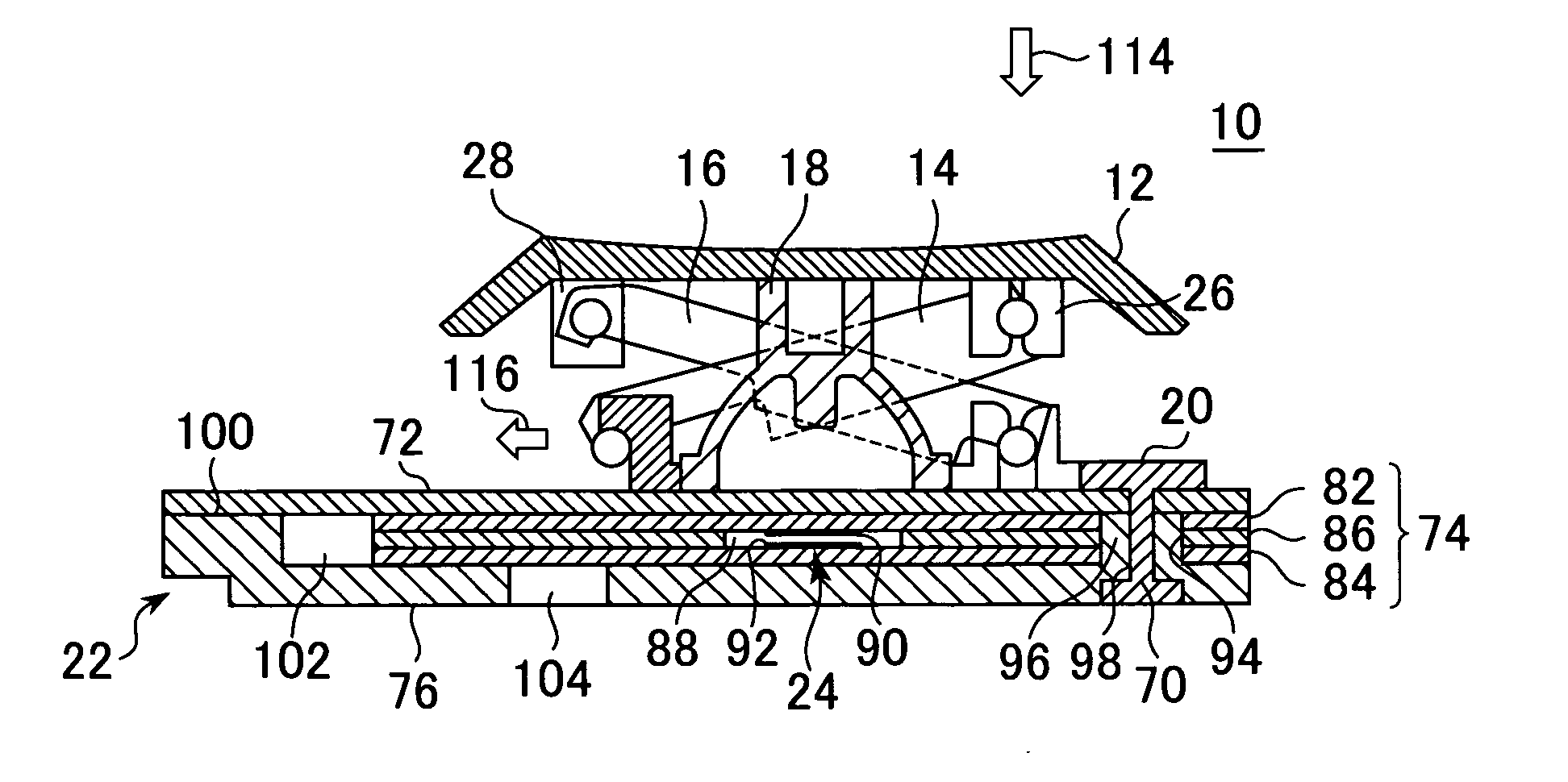
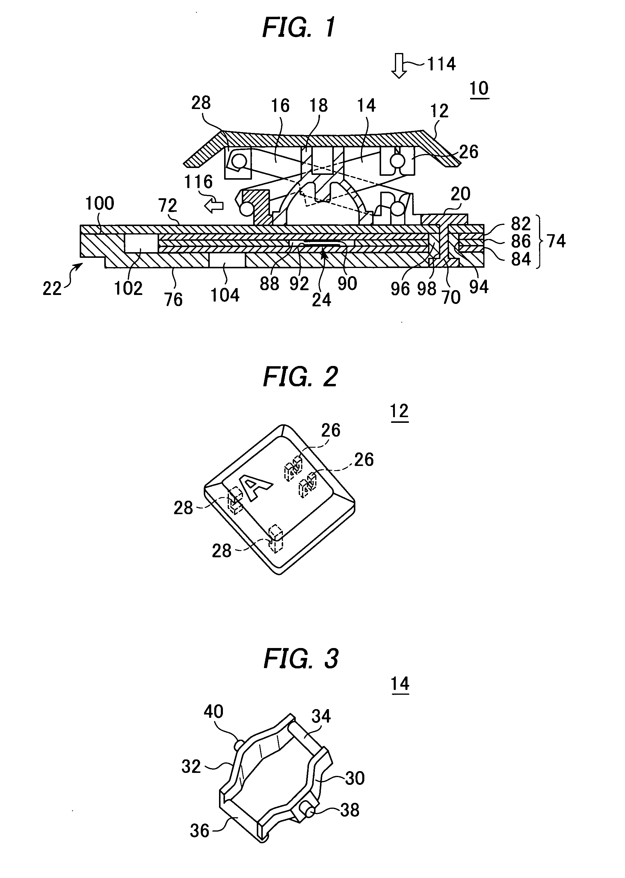
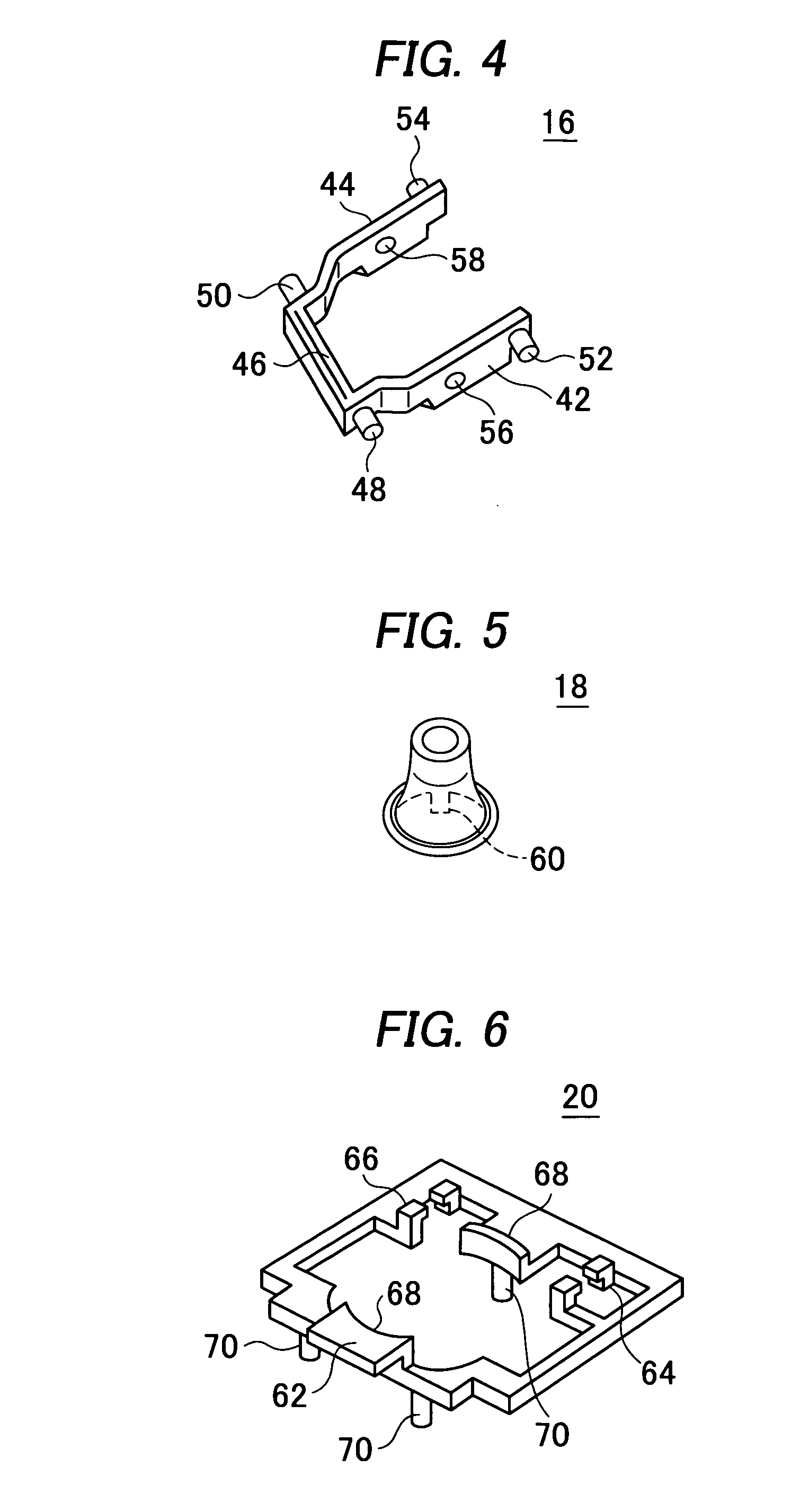
[0026]In the following, an embodiment of a key switch structure in accordance with the present invention will be described in detail with reference to the appended drawings. A key switch 10 in accordance with the embodiment comprises a key top 12, link members 14 and 16, an elastic member 18, a holder 20 and a base part 22, as shown in FIG. 1, so as to allow a contact 24 arranged in the base part 22 to close in response to the key top 12 being depressed.

[0027]On the surface, or upper face, of the key top 12, there may be letters or symbols printed. On the rear side of the key top 12, as shown in FIG. 2, there are provided a rotation support 26 for rotatably supporting one end of the link member 14, and a slide support 28 for supporting one end of the link member 16 rotatably and movably in a horizontal direction.

[0028]The link members 14 and 16 are rotatably connected to each other at their respective central parts, and have one end thereof supported by the key top and the other end...


PUM

PropertyMeasurementUnit
Circumferenceaaaaaaaaaa

Abstract

A key switch structure is provided whose waterproofing property is improved without affecting a contact of a membrane sheet. The upper surfaces of the membrane sheet, the embossed part and the circumferential bend part of a back plate are formed on one and the same plane, and a thermal sheet is welded to those upper surfaces. The thermal sheet comprises a thermally meltable, adhesive sheet, which will be heated and pressed with heat rollers to be welded to the upper surfaces. The back plate has an air vent hole formed in its bottom portion.

Description

TECHNICAL FIELD[0001]The present invention relates to a key switch structure for a keyboard used as an input device in information processing equipment, measuring instruments, medical instruments, etc., and a method of manufacturing the same.BACKGROUND ART[0002]Conventionally, a keyboard for use in a portable personal computer or the like is so arranged that a key top descends without declining whenever the key top is depressed at any part thereof to ensure so-called smooth operation. For this reason, the conventional key switch structure has its link mechanism provided under the key top. Such a key switch having its link mechanism provided under the key top is disclosed for example in Japanese patent laid-open publication No. 2001-229764.[0003]This key switch 200 has, as shown in FIG. 13, its link mechanism constituted of link members 202 and 204 fixed to the base part 208 of the keyboard with a holder 206. The base part 208 is constituted of a back plate 210 and a membrane sheet 2...

Claims


Application Information

Patent Timeline
IPC IPC(8): H01H9/04H01H11/00
CPCH01H3/125H01H13/86Y10T29/49105H01H2229/028H01H2223/003H01H13/06H01H13/14H01H11/00
Inventor YAMADA, SHIGERUTAKAGI, YASUSHI
Owner OKI ELECTRIC IND CO LTD
Features
  • Generate Ideas
  • Intellectual Property
  • Life Sciences
  • Materials
  • Tech Scout
  • Unparalleled Data Quality
  • Higher Quality Content
  • 60% Fewer Hallucinations
Learn More