Fuel Injection Valve And Method For Co-Injecting A Liquid And A Gaseous Fuel Into The Combustion Chamber Of An Internal Combustion Engine

Active Publication Date: 2011-05-12
WESTPORT FUEL SYST CANADA INC
View PDF16 Cites 43 Cited by
  • Summary
  • Abstract
  • Description
  • Claims
  • Application Information

AI Technical Summary

Benefits of technology

[0017]In other embodiments the restricted flow passage is defined within the valve body and liquid fuel is not routed through a gap between the valve needle and the valve body. The restricted flow passage within the valve body can comprise a restriction orifice

Problems solved by technology

Engines using such a method have been unable to match the power, performance, and efficiency of diesel-fuelled engines, mostly because the amount of fuel that can be introduced in this manner can be limited in certain operating conditions because of the risk of engine knock, which happens when there is premature detonation fuel.
A challenge with substituting gaseous fuels such as natural gas for liquid fuel in an engine designed to be fuelled with liquid fuels such as diesel fuel, is that, compared to liquid fuels like diesel fuel, much higher temperatures and pressures are typicall

Method used


Image

  • Fuel Injection Valve And Method For Co-Injecting A Liquid And A Gaseous Fuel Into The Combustion Chamber Of An Internal Combustion Engine
  • Fuel Injection Valve And Method For Co-Injecting A Liquid And A Gaseous Fuel Into The Combustion Chamber Of An Internal Combustion Engine
  • Fuel Injection Valve And Method For Co-Injecting A Liquid And A Gaseous Fuel Into The Combustion Chamber Of An Internal Combustion Engine

Examples


first embodiment

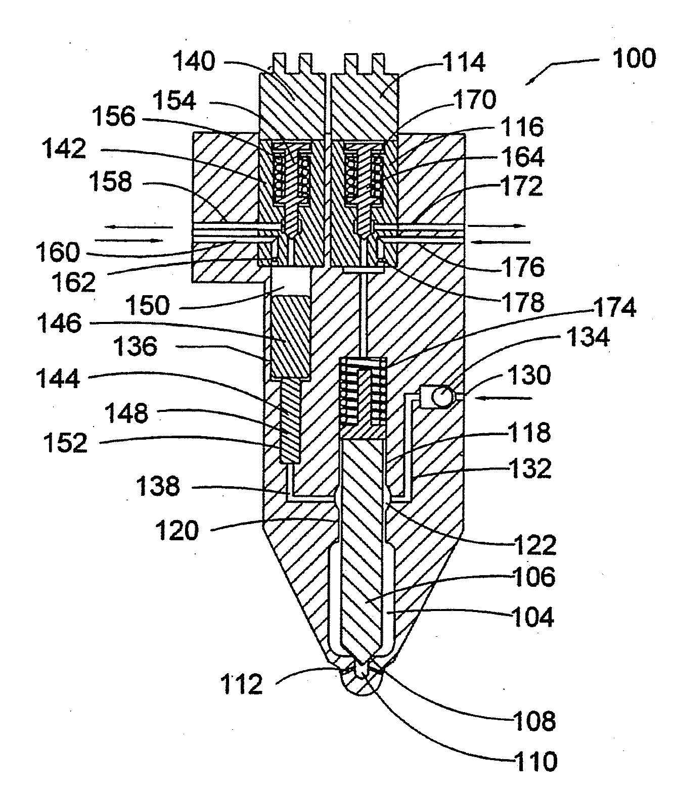
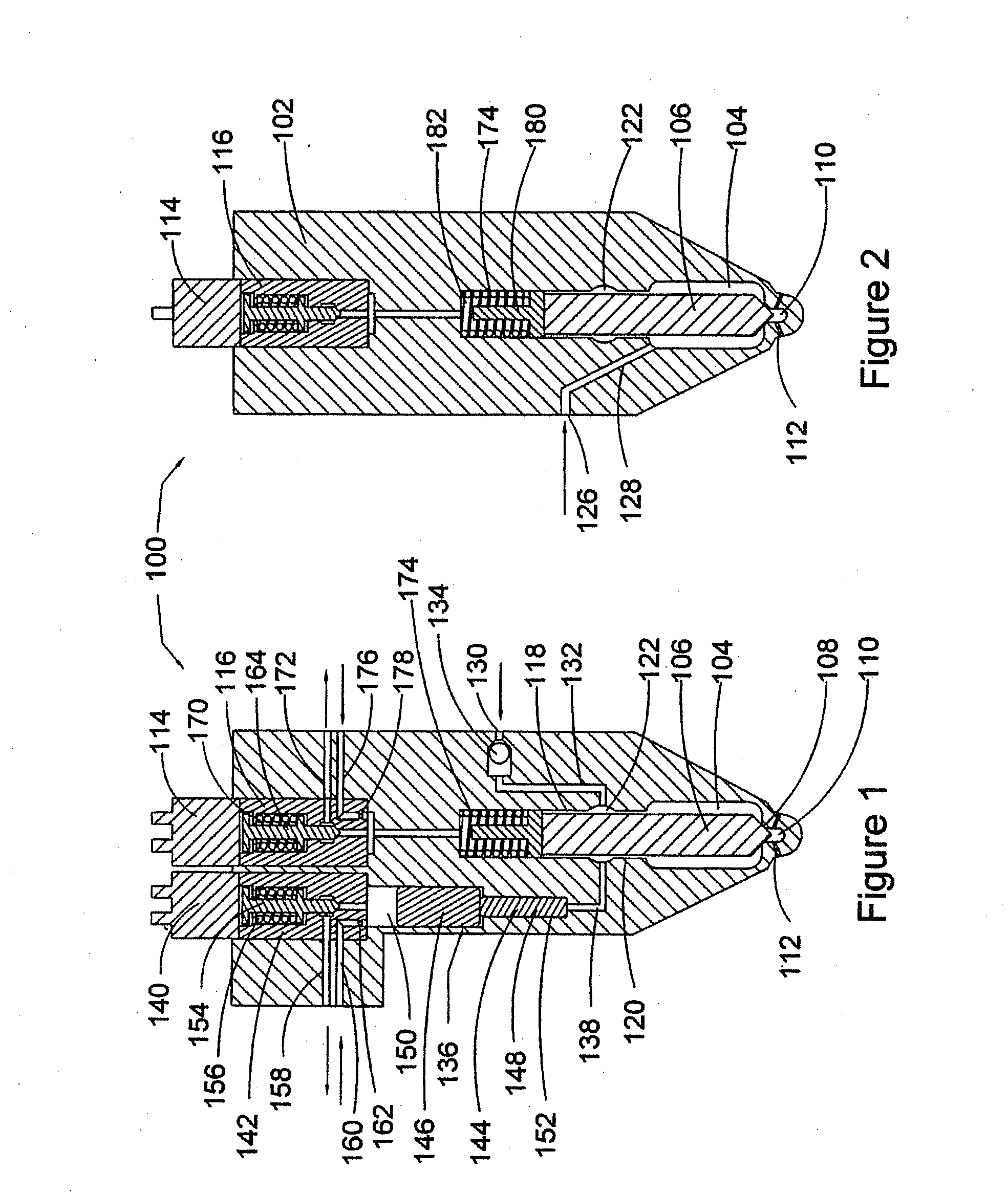
[0051]The aspects of fuel injection valve 100 that relate to the co-injection of gaseous and liquid fuels will now be explained in further detail in relation to the first embodiment illustrated in FIGS. 1 and 2.

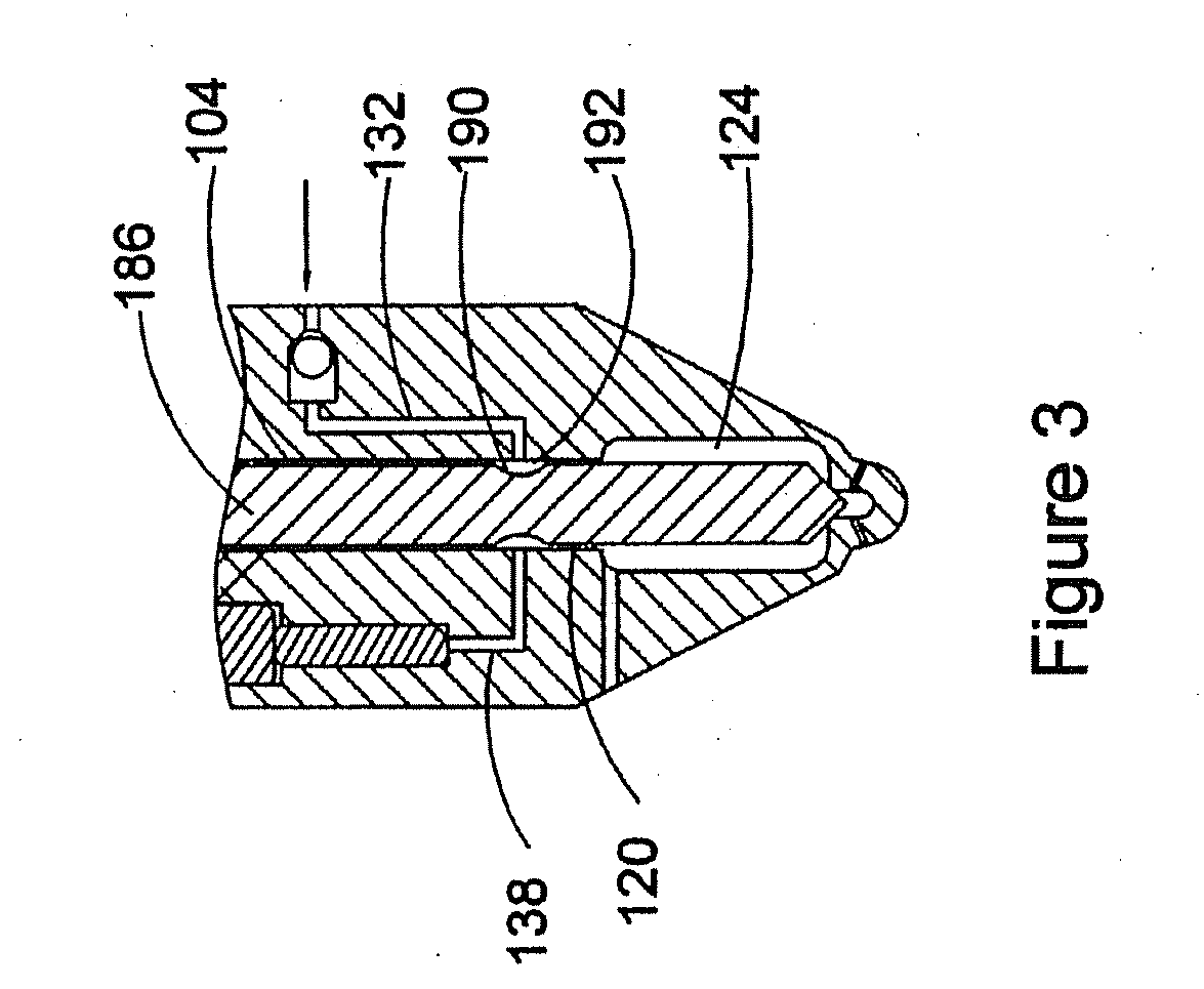
[0052]Liquid fuel is supplied to fuel injection valve 100 at liquid fuel inlet 130 which communicates with the liquid fuel supply line that delivers liquid fuel from liquid fuel inlet 130 to cavity 104. In this embodiment, the liquid fuel supply line comprises liquid fuel passage 132, one-way valve 134, upper chamber 122 and connecting passage 138, which communicates with cylinder 152 of intensifier 136. One-way valve 134 permits flow of liquid fuel into upper chamber 122 and prevents backflow of liquid fuel in the opposite direction. Intensifier 136 meters liquid fuel by the amount that is displaced from cylinder 152 by operation of plunger 144. The liquid fuel supply line further comprises a restricted flow passage that is provided in this embodiment by annular passage 120 ...

third embodiment

[0069]the disclosed fuel injection valve is illustrated in FIGS. 7, 8 and 9. In this embodiment liquid fuel discharged from intensifier 136 flows to cavity 104 through connecting passage 138, and a restricted flow passage provided by restriction orifice 320 in passage 322. Restriction orifice 320 prevents substantially any liquid fuel from leaking into cavity 104 through passage 322, except when the metered amount of liquid fuel is discharged from intensifier 136. An additional one-way valve (not illustrated) can be installed in passage 322 upstream of restriction orifice 320 to allow the one-way flow of liquid fuel from intensifier 136 to cavity 104 only when the pressure of the liquid fuel is over a predetermined value.

[0070]Fuel injection valve 300 operates similarly to the valve described in the first and second embodiments. Liquid fuel is drawn into intensifier 136 when solenoid valve 140 is energized, and pressurized liquid fuel is discharged from intensifier 136 into cavity 1...

fourth embodiment

[0071]In FIGS. 10 and 11 fuel injection valve 400 illustrates the disclosed fuel injection valve. In this embodiment connecting passage 138 communicates with cavity 104 through two flow paths. One flow path comprises connecting passage 138, upper chamber 122 and a first restricted flow passage provided by annular gap 120, and the other flow path comprises a second restricted flow passage provided by passage 422 and restriction orifice 420. Passage 422 further comprises one-way valve 424, positioned upstream of restriction orifice 420. Liquid fuel is supplied from inlet 130 through the liquid fuel supply line which comprises, passage 132, upper chamber 122, connecting passage 138, the first restricted flow passage and the second restricted flow passage into cavity 104. Gaseous fuel is supplied from gaseous fuel inlet 126 through passage 128 into cavity 104.

[0072]Fuel injection valve 400 operates similarly to the valves described in the previous embodiments. The metered amount of liqu...


PUM


Abstract

A fuel injection valve co-injects a liquid and a gaseous fuel into the combustion chamber of an internal combustion engine. A solid needle regulates the injection of liquid and gaseous fuels from a cavity in the fuel injection valve into the combustion chamber when the needle is lifted to its open position. In preferred embodiments, liquid fuel is metered and pressurized in an intensifier's cylinder provided within the valve body and the liquid fuel is delivered through a restricted flow passage into the cavity where it mixes with the gaseous fuel. The restricted flow passage can be formed by a small passage formed in the valve body or an annular passage between the needle and the valve body.

Description

CROSS-REFERENCE TO RELATED APPLICATION(S)[0001]This application is a continuation of International Application No. PCT / CA2009 / 000590, having an international filing date of Apr. 30, 2009, entitled “Fuel Injection Valve And Method For Co-Injecting A Liquid And A Gaseous Fuel Into The Combustion Chamber Of An Internal Combustion Engine”. The '590 international application claimed priority benefits, in turn, from Canadian Patent Application No. 2,633,846 filed Jun. 27, 2008. The '590 international application is hereby incorporated by reference herein in its entirety.FIELD OF THE INVENTION[0002]The present invention relates to a fuel injection valve and a method for co-injecting a liquid and a gaseous fuel into the combustion chamber of an internal combustion engine. Both fuels are injected into the combustion chamber of the internal combustion engine when the needle is lifted from its seated position.BACKGROUND OF THE INVENTION[0003]Because of its ready availability, low cost and pote...

Claims


Application Information

Patent Timeline
IPC IPC(8): F02M43/04
CPCF02M43/04F02M57/025F02M63/0049Y02T10/36F02D19/081F02M21/0263F02D19/0642F02D19/0689F02D19/0694Y02T10/32Y02T10/30
Inventor MUMFORD, DAVIDMUNSHI, SANDEEP
Owner WESTPORT FUEL SYST CANADA INC
Why Eureka
Try Eureka