Air manifold for ventilated seat or bed

Active Publication Date: 2011-05-12
IGB AUTOMOTIVE
View PDF19 Cites 145 Cited by
  • Summary
  • Abstract
  • Description
  • Claims
  • Application Information

AI Technical Summary

Benefits of technology

[0008]The present invention provides an air manifold for a ventilated seat or bedding that overcomes the deficiencies of the prior art. The present air manifold includes an air permeable structure disposed between the cushioning element and supporting structure of a seat. The air permeable structu

Problems solved by technology

One technical difficulty in the field of ventilated seats is the structure and arrangement of the manifold for delivery and/or exhaust of air to and from the air permeable elements of the seat.
This “porous” manifold exhibits significant hydraulic resistance, limiting the airflow and thus th

Method used


Image

  • Air manifold for ventilated seat or bed
  • Air manifold for ventilated seat or bed
  • Air manifold for ventilated seat or bed

Examples


Embodiment Construction

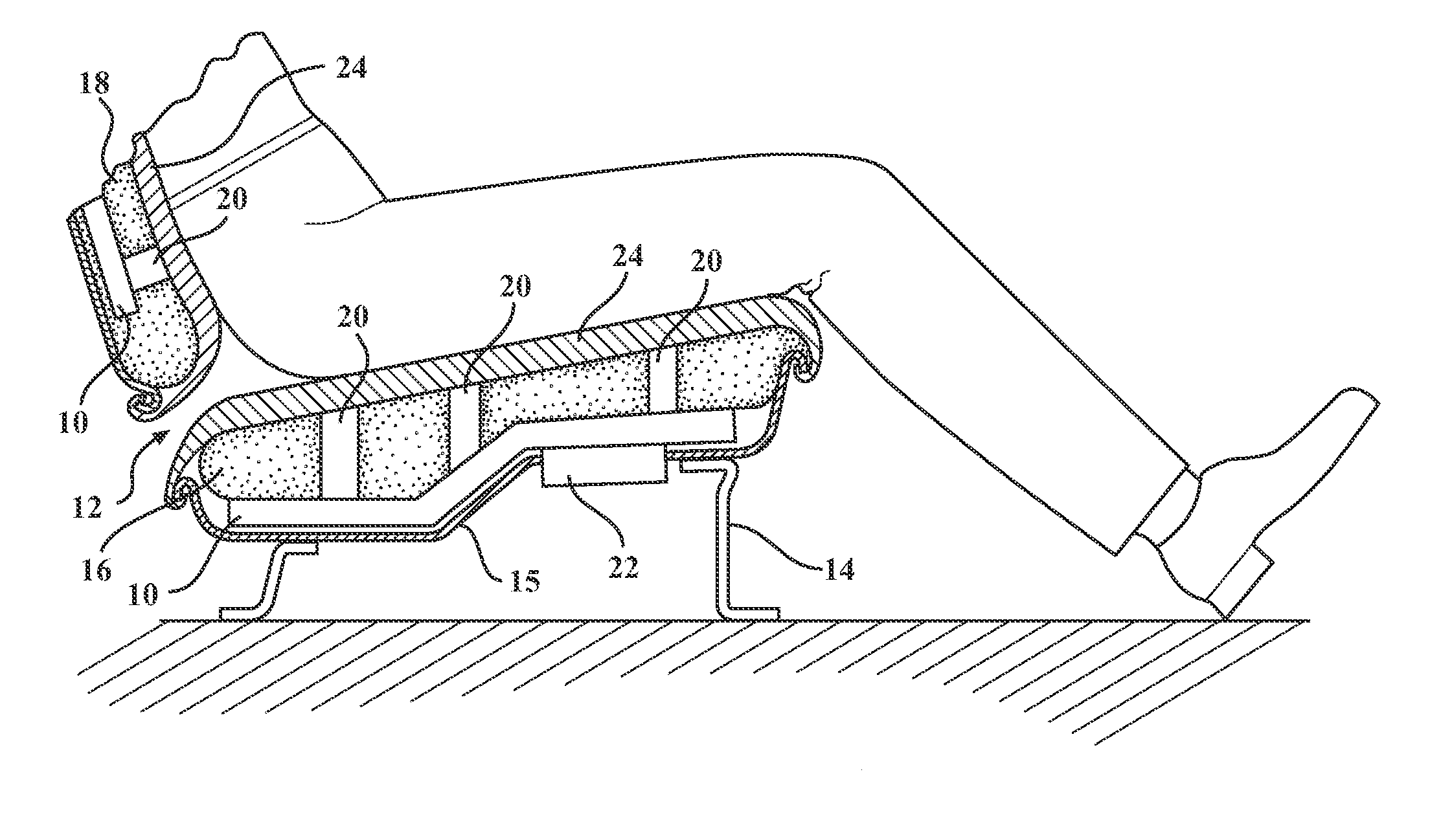
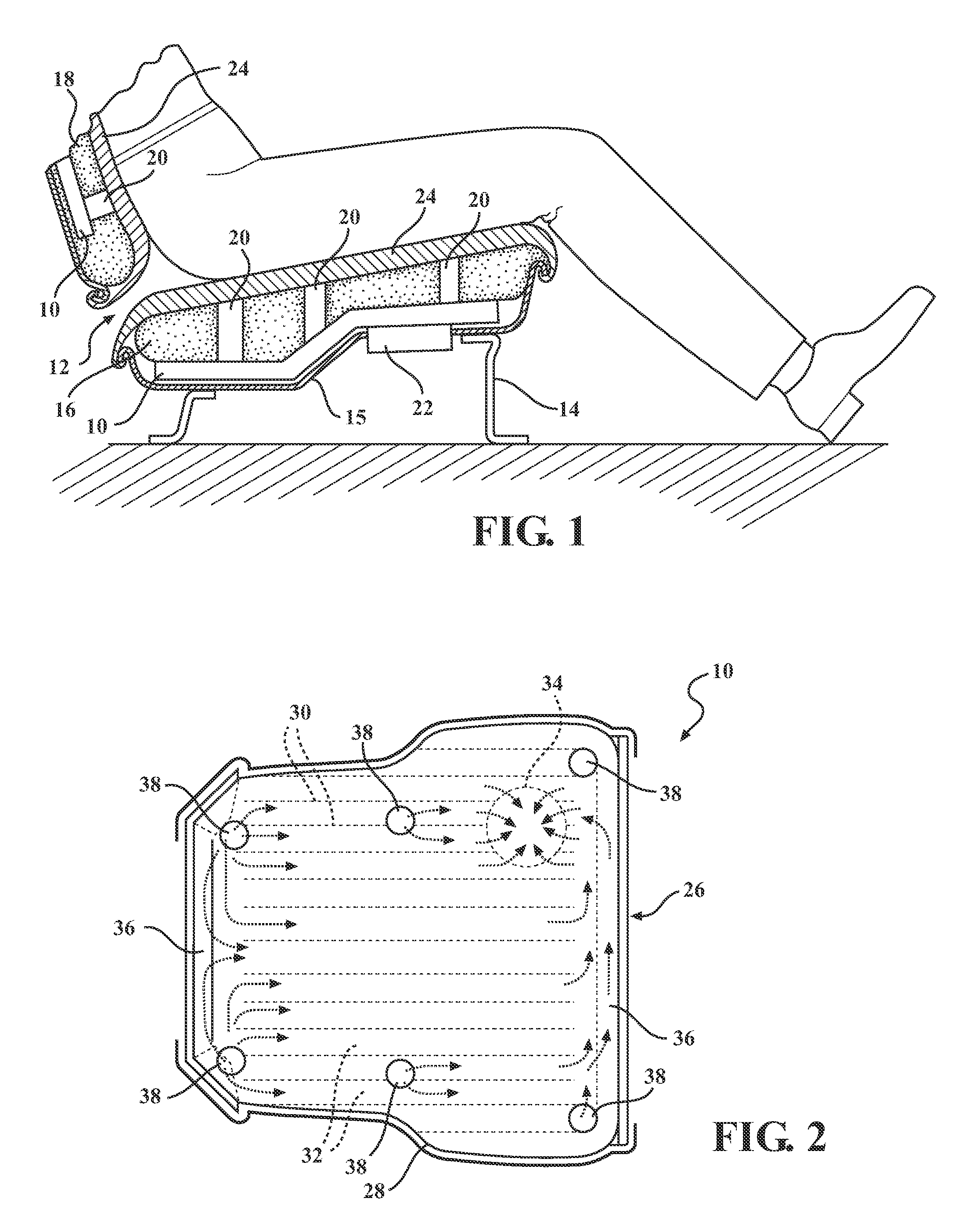
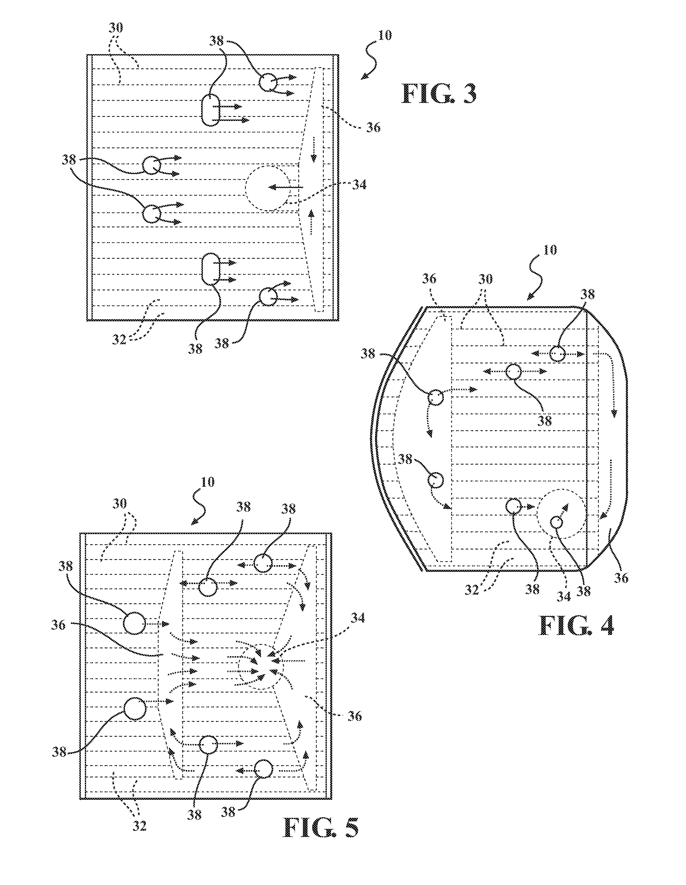
[0056]Referring now to the drawings in detail, numeral 10 generally indicates an air manifold for a ventilated seat or bed in accordance with the present invention. The air manifold 10 provides for the distribution of air to an occupant facing surface of an occupant support such as a vehicle seat, a chair, a bed, or similar, while having low hydraulic resistance. The air manifold 10 is constructed from low cost standardized components by relatively simple production equipment. In the following description, like reference numbers refer to similar structure in the various embodiments disclosed.

[0057]Turning first to FIG. 1, a ventilated occupant support 12 in accordance with the invention includes a frame 14 or other suitable solid support structure or deflectable surface, and a seat cushion 16 and seat backrest cushion 18 supported by the frame. The frame 14 may include a seat pan 15 which supports the seat cushion 16. At least one of the seat cushion 16 and the seat backrest 18 is m...


PUM


Abstract

An air manifold includes a sheet-like body including first and second spaced, opposing walls and a sealed perimeter. A plurality of divider walls connects the first and second walls together and defines a plurality of air channels within the body. An opening in the body defines an air port cooperable with an air mover. The air port is in fluid communication with the air channels. At least one zone inside the body is free of the divider walls. A group of the air channels are in fluid communication with each other through one the zone. A plurality of air vents located in the first wall are in fluid communication with at least one of the air channels. The air manifold is disposable between a seat cushion element and a structural support of a seat. The first wall of the air manifold faces a backside surface of the seat cushion element.

Description

CROSS REFERENCE TO RELATED APPLICATION[0001]This application claims the priority of U.S. Provisional Application No. 61 / 260,548 filed Nov. 12, 2009.TECHNICAL FIELD[0002]This invention relates to the field of comfort systems for occupant supports, and more particularly to an air manifold for vehicular and non-vehicular seating and bedding.BACKGROUND OF THE INVENTION[0003]Conventional ventilated seats include a seat trim cover made of fabric or leather on which a seat occupant's body contacts, and an air permeable layer located under the seat cover. The air permeable layer rests on a cushioning element, for example a bun of polyurethane foam, coconut fiber, cotton mat, etc. An air manifold conducts air flow into or out of the air permeable layer or the whole cushioning element. In such seats, the source of the air pressure or partial vacuum (fan, blower, seat air conditioning unit or a ducting from a vehicular air conditioning unit) is connected to the seat internal manifold.[0004]The...

Claims


Application Information

Patent Timeline
IPC IPC(8): A47C7/74F16L41/02B60N2/56
CPCA47C7/744B60N2/5642A47C21/044B60N2/565Y10T137/85938
Inventor AXAKOV, DMITRIJOSHI, RAGHVENDRA
Owner IGB AUTOMOTIVE
Why Eureka
Try Eureka