Motor control center unit withdraw with door closed

a technology of motor control center unit and door closure, which is applied in the direction of electrical apparatus construction details, electrical apparatus casing/cabinet/drawer, electrical apparatus mounting, etc., can solve the problems of increasing the risk of operator inadvertent contact with elements within the enclosure, access to components, and provision of network and power signals, so as to reduce the risk of operator contact. , the effect of reducing the risk

Active Publication Date: 2011-05-12
ROCKWELL AUTOMATION TECH
View PDF25 Cites 49 Cited by
  • Summary
  • Abstract
  • Description
  • Claims
  • Application Information

AI Technical Summary

Benefits of technology

[0007]An electrical enclosure is provided wherein an electrical component can be moved between various positions (e.g., connected, disconnected, test, etc.) without opening an enclosure door thereby eliminating or substantially reducing the risk of an operator contacting a live component within the enclosure. More particularly, an electrical enclosure is provided that supports a component for movement between a withdrawn position, a test position, and an inserted position. A handle is accessible by an operator from an exterior of the enclosure and is config

Problems solved by technology

A particular issue that arises in some packaged electrical systems is the access to the components, and provision of network and power signals to the component

Method used


Image

  • Motor control center unit withdraw with door closed
  • Motor control center unit withdraw with door closed
  • Motor control center unit withdraw with door closed

Examples


Embodiment Construction

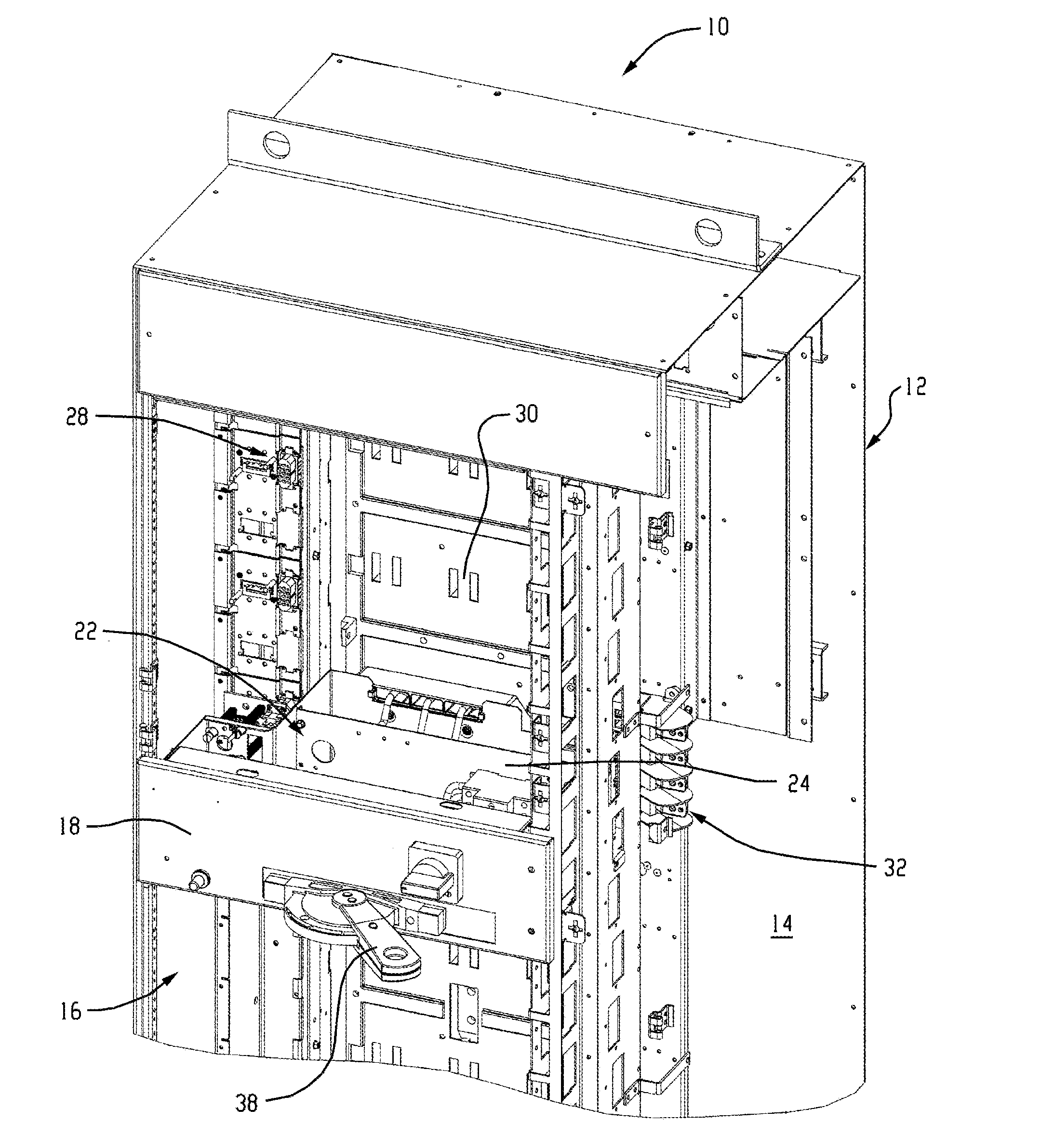
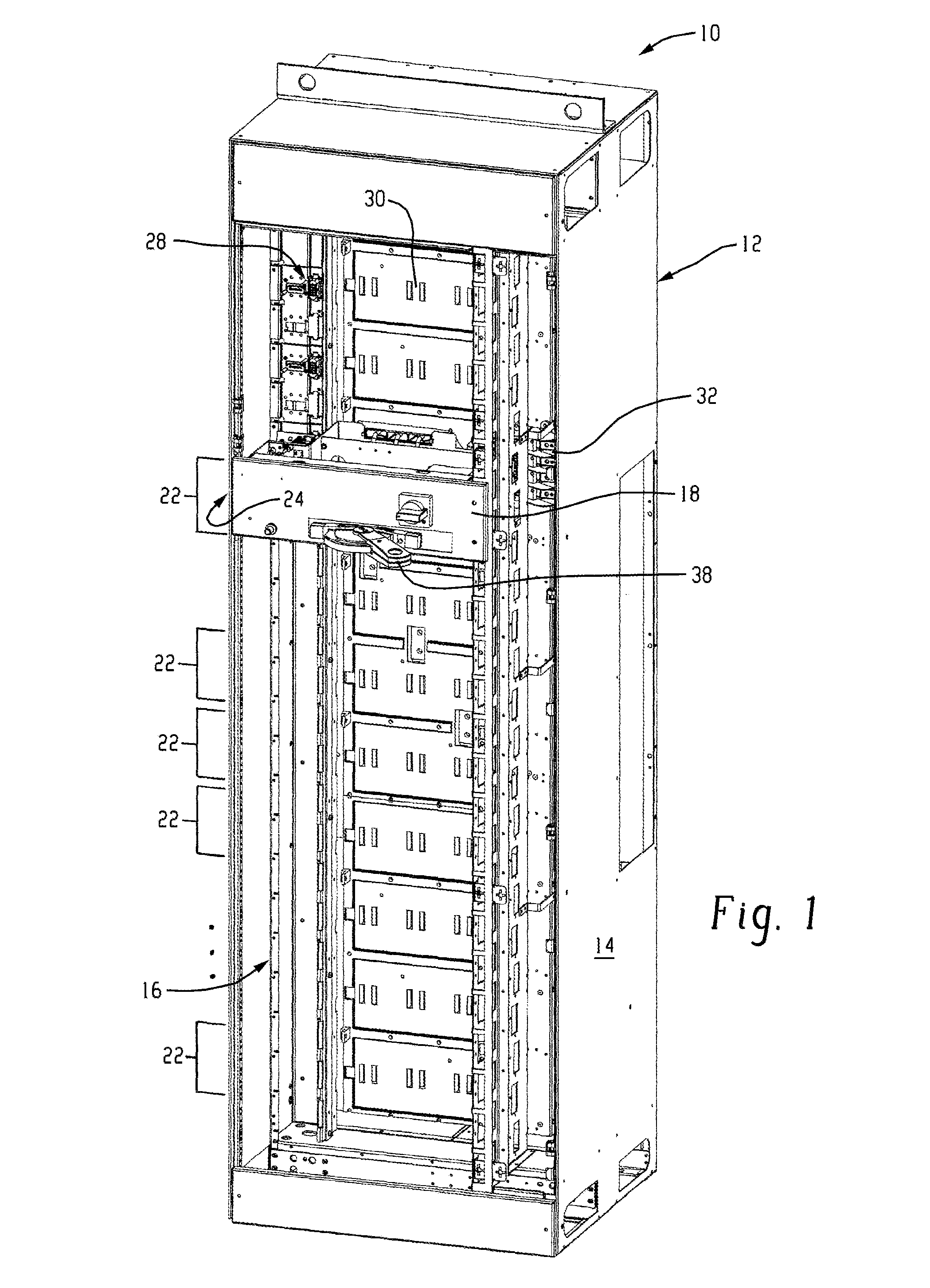
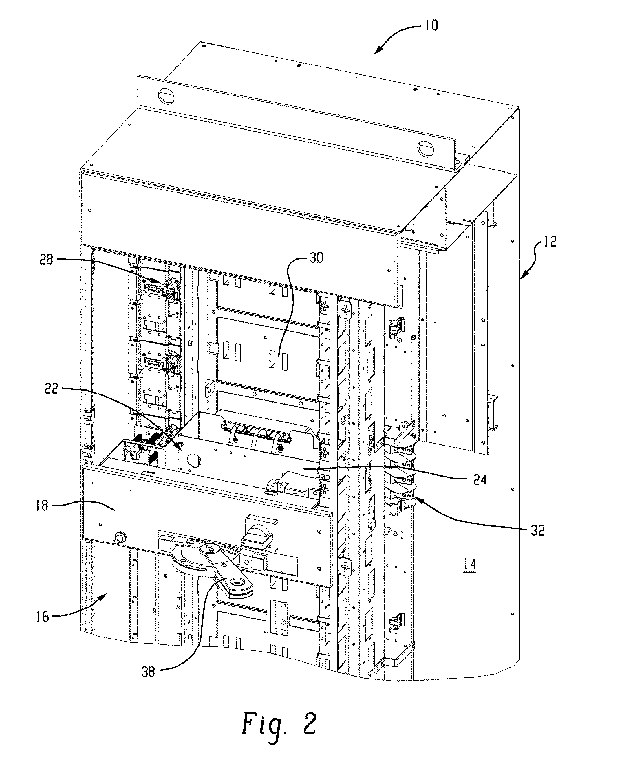
[0022]In FIGS. 1 and 2, an electrical enclosure cabinet in the form of a motor control cabinet (MCC) 10 is illustrated including an exemplary component support in accordance with the invention. The MCC 10 includes an enclosure 12 that houses various electrical components. The enclosure 12 will typically be formed of heavy gauge sheet metal, although other enclosures, such as made of reinforced plastic may sometimes be used. The enclosure generally includes a top, a bottom, and sidewalls forming a shell 14 having a main interior volume 16 in which components and component supports are placed. The interior volume 16 may be subdivided into compartments that each receive particular components, typically components interconnected to form a portion of an overall process control or monitoring system. Each compartment may be accessed through a main door 18, which may be secured in place with suitable fasteners such as screws or the like to hold the door 18 closed over the interior volume du...


PUM

PropertyMeasurementUnit
Volumeaaaaaaaaaa

Abstract

An electrical enclosure wherein an electrical component can be moved between various positions (e.g., connected, disconnected, test, etc.) without opening an enclosure door. The electrical enclosure supports a component for movement between a withdrawn position, a test position, and an inserted position. A handle is accessible by an operator from an exterior of the enclosure and is configured to move the component between the respective positions without having to open the enclosure. The handle is integral with the enclosure and thus an operator needs no special tool or other device to effect movement of the electrical component between its respective positions.

Description

RELATED APPLICATIONS[0001]The present application claims priority to U.S. Provisional Application Ser. No. 61 / 258,960 filed on Nov. 6, 2009, and U.S. Provisional Application Ser. No. 61 / 372,574 filed on Aug. 11, 2010, both of which are hereby incorporated herein by reference in their entirety.BACKGROUND OF THE DISCLOSURE[0002]The present invention relates generally to the field of packaged electrical components, and more particularly to a novel connector arrangement and system for interconnecting supported components in an enclosure with prewired connectors within the enclosure.[0003]A wide range of packaged electrical and electronic systems have been developed that control industrial, commercial, marine and other processes. In general, such systems include both electronic monitoring and control equipment, as well as switchgear, controllers, and other power electronic equipment that drive loads. In an industrial setting, for example, motor control centers (MCCs) are large systems th...

Claims


Application Information

Patent Timeline
IPC IPC(8): H05K5/00H05K7/02H01R43/00
CPCH05K7/1409H05K7/1411Y10T29/49117H02G5/06H05K7/14H01R13/53H02B1/36
Inventor LEHTOLA, GREGORY DAVIDMEYER, DEANOMOTO, ARNALDO HIROYUKIKRAUSE, PAULITO, FABIO KAZUOBAUER, JR., STEVEN J.FREITAS, JOAO JORGE MARTINS
Owner ROCKWELL AUTOMATION TECH
Why Eureka
Try Eureka