Compact display flex and driver sub-assemblies
a flexible circuit and driver technology, applied in the direction of optics, printed circuit aspects, instruments, etc., can solve the problems of increasing the size of the space within the device becoming increasingly limited, and the electronic device and the display being increasingly smaller. , to achieve the effect of less space, narrower width and less spa
- Summary
- Abstract
- Description
- Claims
- Application Information
AI Technical Summary
Benefits of technology
Problems solved by technology
Method used
Image
Examples
first embodiment
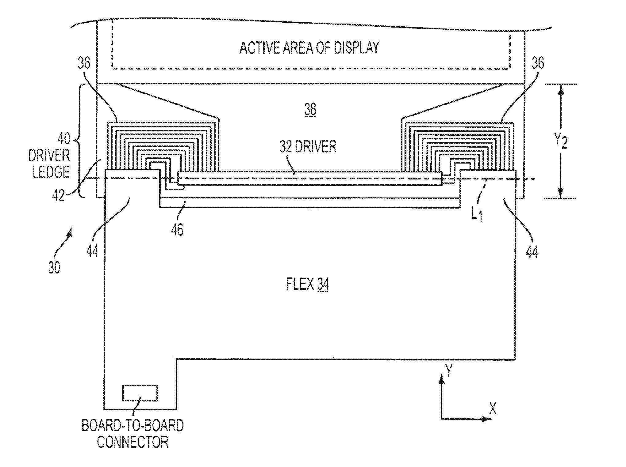
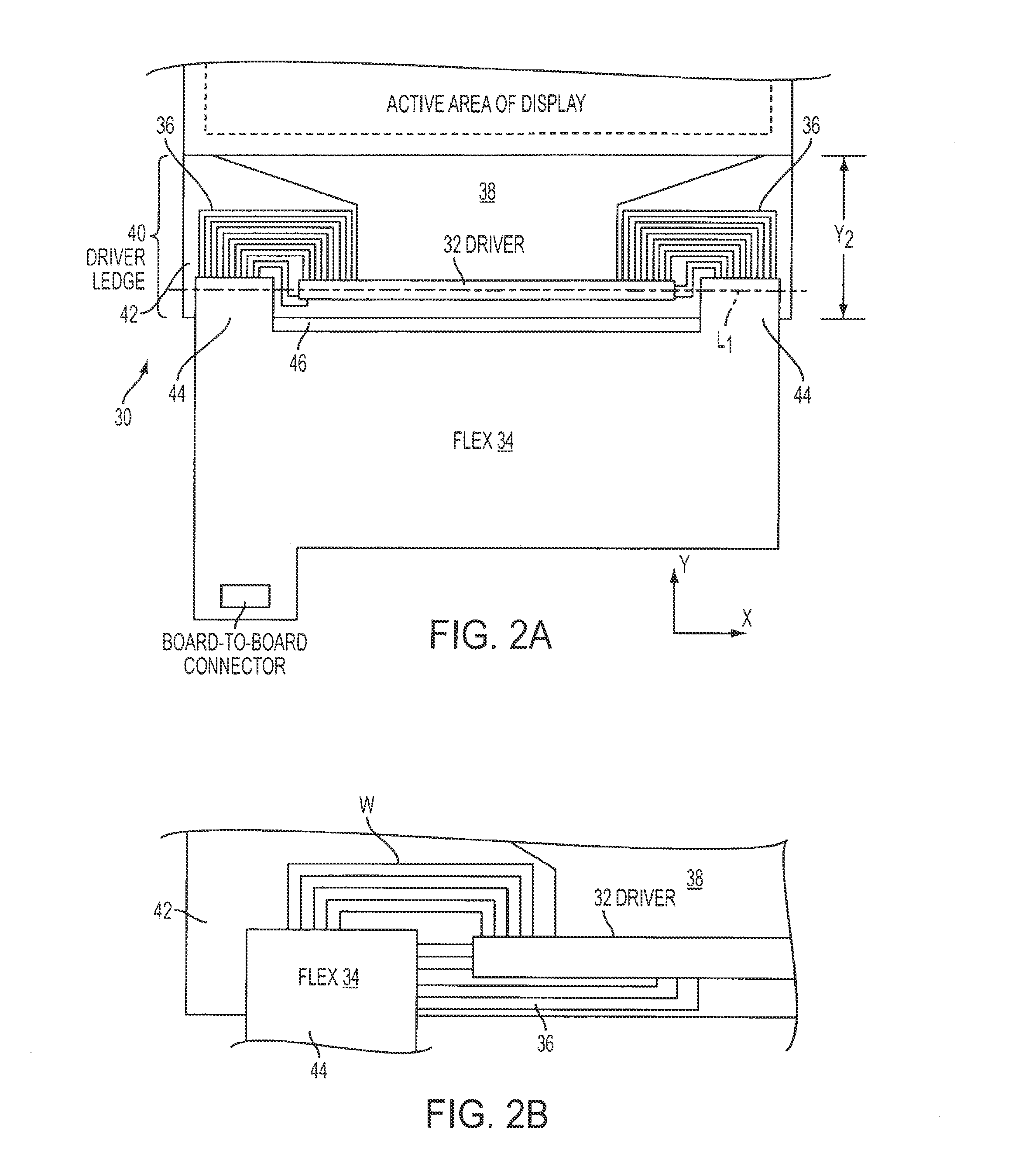
[0028]FIGS. 2A-2B illustrate a compact flex and driver sub-assembly in accordance with the present invention. Sub-assembly 30 can include driver 32, flex 34, flex-to-driver fan-out 36, and driver-to-active area fan-out 38, all of which can be disposed (at least in part) on driver ledge 40 of pixel activation substrate 42, directly or indirectly. In one embodiment of the present invention, substrate 42 can be made of transparent, non-conductive material, e.g., glass.
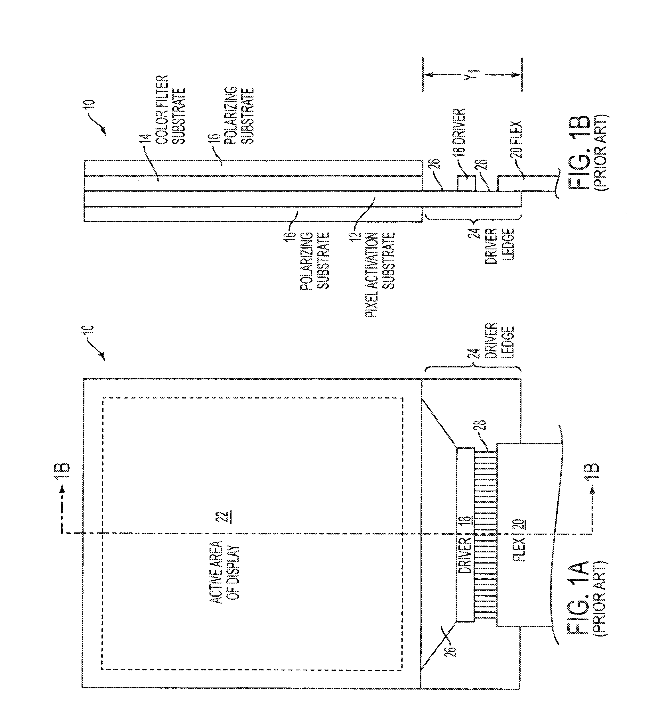
[0029]To reduce the Y dimension of the driver ledge so that length Y2 of ledge 40 is less than length Y1 of ledge 24 of FIG. 1, the space on driver ledge 42 occupied by portions of flex 20 and fan-out 28 in conventional display assembly 10 can be reduced or eliminated. This can be accomplished by attaching multiple smaller attachment portions 44 of flex 34 to areas of substrate 42 that were unused in conventional display assembly 10, instead of attaching the flex to the pixel activation substrate along the entire width of...
second embodiment
[0035]FIG. 3 illustrates a compact flex and driver sub-assembly in accordance with the present invention. Flex and driver sub-assembly 50 can include driver 52, flex 54, flex-to-driver fan-out 56, and driver-to-active area fan-out 58, all of which can be disposed (at least in part) on driver ledge 60 of pixel activation substrate 62, directly or indirectly.
[0036]To reduce the space within the electronic device that is occupied by flex 54, flex 54 can have a maximum width that is less than that of flex 20 of FIG. 1 and driver 52 (i.e., maximum width X54 of flex 54 can be less than width X52 of driver 52). Because flex 54 has a smaller width, the area of flex 54 that can be attached to pixel activation substrate 62 also can be smaller. As a result, flex 54 may not be able to accommodate as many wires. Again, a high speed serial interface may be employed to permit all desired signals to be transmitted using fewer wires. Composite wires, such as those described below with respect to FIG...
third embodiment
[0039]FIG. 4 illustrates a compact flex and driver sub-assembly in accordance with the present invention. Flex and driver sub-assembly 70 can include driver 72, flex 74, flex-to-driver fan-out 76, and driver-to-active area fan-out 78 disposed on driver ledge 80 of pixel activation substrate 82, directly or indirectly.
[0040]Sub-assembly 70 can be a combination of sub-assemblies 30 and 50. For example, flex 74 can have maximum width X74 that is less than width X72 of driver 72. Because flex 74 is narrower, the attachment portion of flex 74 for attaching the flex to substrate 82 also may be smaller. This can permit flex 74 to be attached to previously unused portions of substrate 82. For example, flex 74 can be attached to substrate 72 so that the flex intersects the longitudinal axis of driver 72.
[0041]Flex-to-driver fan-out 76 also can be configured similarly to those of sub-assemblies 30 and 50. Flex-to-driver fan-out 76 can have wires that emanate from one or multiple edges of flex...
PUM
 Abstract
Description
Claims
Application Information
 - R&D
- Intellectual Property
- Life Sciences
- Materials
- Tech Scout
- Unparalleled Data Quality
- Higher Quality Content
- 60% Fewer Hallucinations
Browse by: Latest US Patents, China's latest patents, Technical Efficacy Thesaurus, Application Domain, Technology Topic, Popular Technical Reports.
© 2025 PatSnap. All rights reserved.Legal|Privacy policy|Modern Slavery Act Transparency Statement|Sitemap|About US| Contact US: help@patsnap.com


