Interface

a technology for locking interfaces and interfaces, applied in the direction of coupling device connections, coupling parts engagement/disengagement, testing/measuring connectors, etc., can solve the problems of contact crushing, high torque requirements, and tendency to cross-thread easily

Active Publication Date: 2011-05-12
VIRGINIA PANEL
View PDF45 Cites 6 Cited by
  • Summary
  • Abstract
  • Description
  • Claims
  • Application Information

AI Technical Summary

Benefits of technology

[0016]In a preferred embodiment, the present invention is an interface having a receiver and a test adapter. The receiver comprises a receiver body, a latch post connected to the receiver body and a receiver guide member. The latch post comprises a latch post body and a latch post tip. The test adapter comprises a test adapter frame, an engagement assembly mounted to the test adapter frame and a test adapter guide member for providing alignment of the test adapter with the receiver. The engagement assembly comprises a drive shaft having first and second ends, the second end of the drive shaft having a threaded interior portion, a drive knob connected to the first end of the drive shaft and a drive screw. The drive screw comprises a threaded exterior portion, the threaded exterior portion of the drive screw engaging with the threaded interior portion of the drive shaft and an engagement member extending longitudinally away from the threaded portion of the drive screw for engaging the latch post in the receiver during engagement of the test adapter with the receiver. The drive shaft may comprise an opening at the second end and a drive nut within the opening in the second end, the drive nut having a threaded interior portion. The interface may further comprise a drive screw housing surrounding the springs, the drive screw housing having a recessed portion adjacent the enlarged portion of the spring when, the engagement assembly is in a disengaged position. The latch post may further comprise a latch post neck between the latch post body and the latch post tip and wherein the latch post neck has a smaller circumference than the latch post tip. The engagement member may comprise a plurality of springs extending from the drive screw, wherein the plurality of springs engage with the latch post tip when the test adapter is mated with the receiver. The test adapter guide member may comprise a rectangular-shaped guide mounted to the test adapter frame and protruding from a face of the test adapter and the receiver guide member may comprise a bushing mounted to the receiver frame and having an opening matching the rectangular shape of the test adapter guide member to permit the test adapter guide member to be inserted into the opening in the bushing and thereby align the test adapter with the receiver. In another embodiment, the test adapter guide member comprises a guide post mounted to the test adapter frame and protruding from a face of the test adapter and the receiver guide member comprises a hole in the receiver frame having an opening matching the guide post to permit the guide post to be inserted into the opening in the receiver frame and thereby align the test adapter with the receiver. The engagement member in the test adapter may comprise a spring or a plurality of springs and a locking tab on one end of each the spring.

Problems solved by technology

This system suffered from significant problems of the ITA tilting to some degree and thereby causing contacts to be crushed.
Although they do not need lubrication, they have a tendency to cross-thread easily.
The systems that employ helical grooves typically only require 180° of rotation to achieve full engagement but require a high amount of torque and the use of lubrication to maintain an only somewhat smooth feel during the process of engaging and disengaging.
Even with the use of lubrication, these systems show a consistent pattern of extremely high wear on some of the components involved in the engagement procedure.
The torque and the wear issues worsen over the cycle life of the system.
Also, considering the geometry of these systems, the lubrication is required to be applied in an area that threatens sensitive electronic components.

Method used


Image

  • Interface
  • Interface
  • Interface

Examples


second embodiment

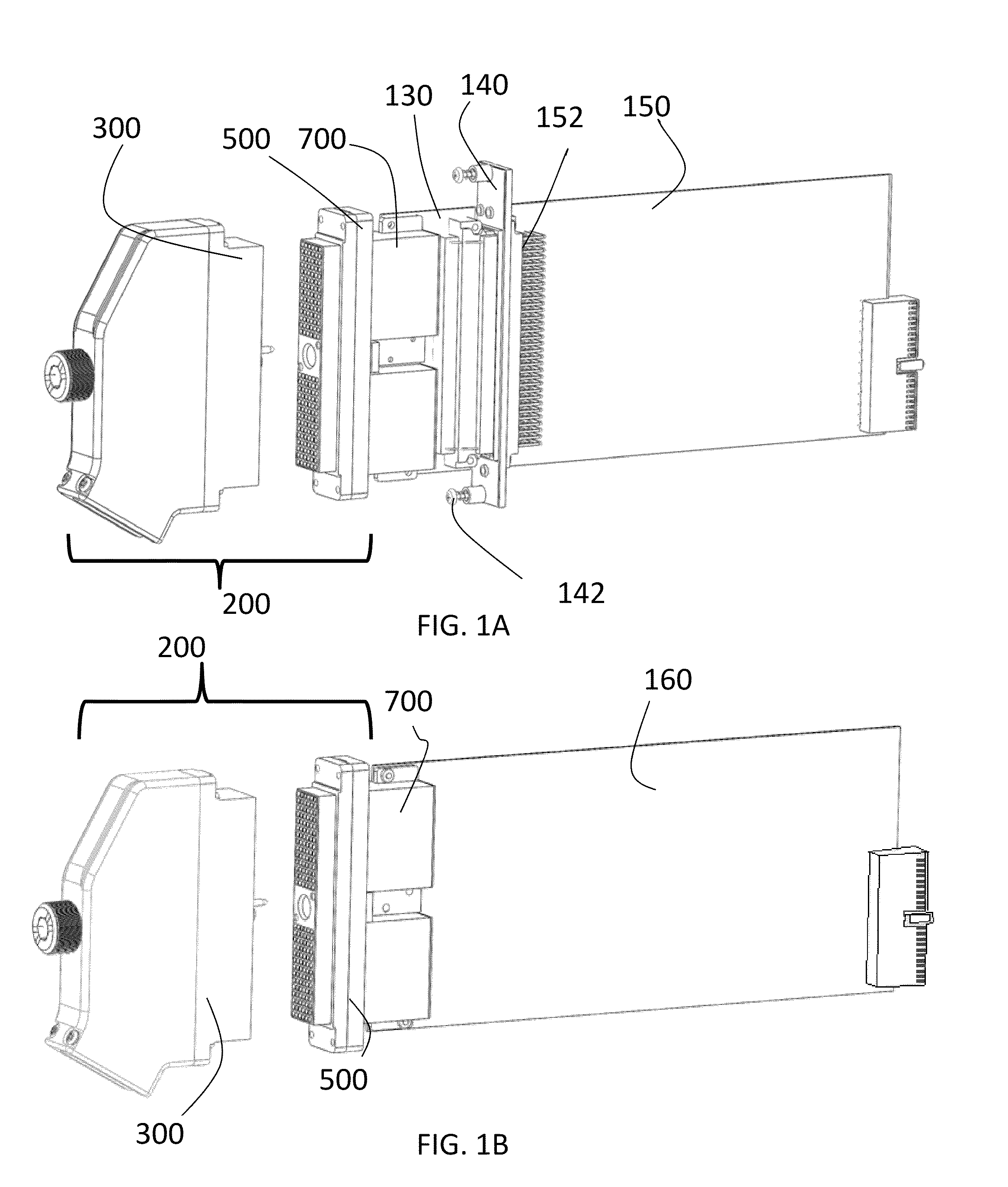
[0062]FIG. 1B illustrates a second embodiment in which an interface device 200, again comprised of a receiver 500 and a test adapter 300, is connected on the receiver side to a header 700. The header 700 is connected directly to a PXI card 160.

third embodiment

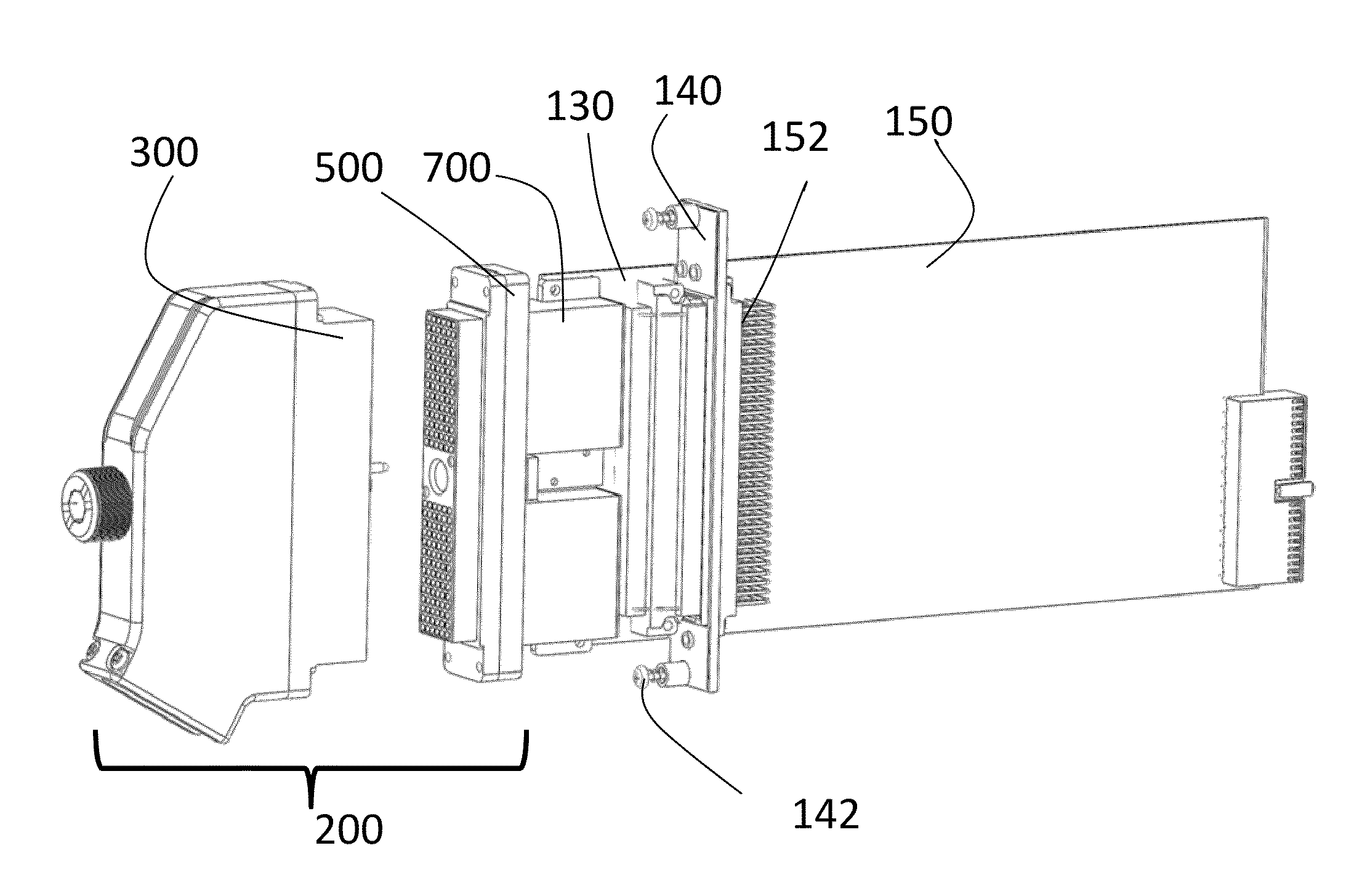
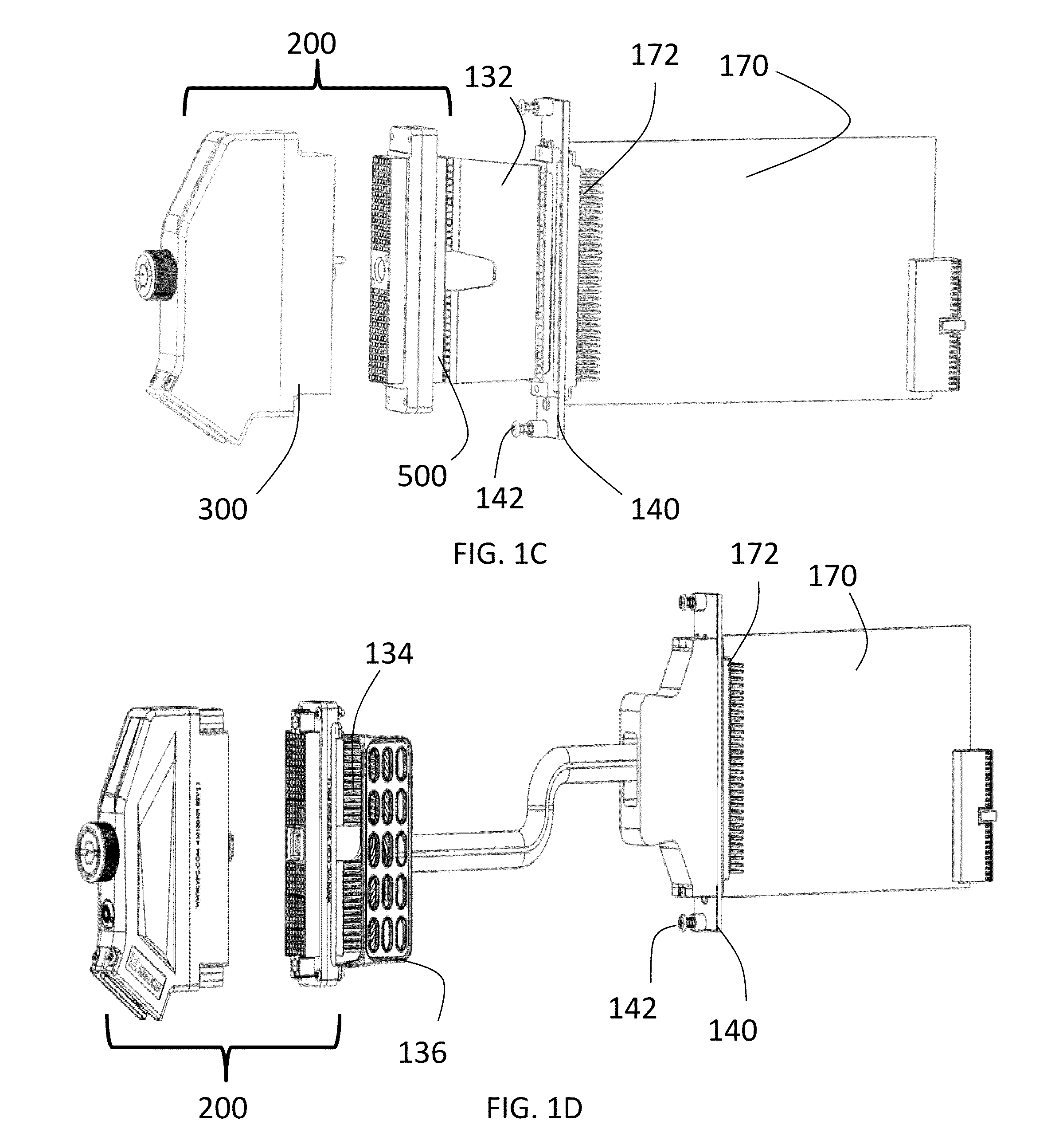
[0063]FIG. 1C illustrates a third embodiment in which an interface device 200 is connected on the receiver side to a flex circuit 132. The flex circuit 132 is connected to a header 172 of a PXI card 170 that extends through an opening in an ejector face plate 140. The ejector face plate has means, such as a screw 142, near each end to connect the face plate 140 to a chassis.

fourth embodiment

[0064]FIG. 1D illustrates a fourth embodiment in which an interface device 200 is connected on the receiver side to discrete wiring 134 via crimp contacts. A receiver strain relief assembly 136 to provide support for the wiring 134. The wires 134 are connected to a header 172 of a PXI card 170 that extends through an opening in an ejector face plate 140. The ejector face plate has means, such as a screw 142, near each end to connect the face plate 140 to a chassis. A stress relief plate 136, shown in greater detail in FIG. 15, may be used to support the discrete wiring 134.

[0065]A first preferred embodiment of the interface device 200 comprised of test adapter 300 and receiver 500 is shown in greater detail in FIGS. 2-5. A first preferred embodiment of a test adapter 300 in accordance with the present invention is described with reference to FIGS. 3-4. The test adapter 300 has a frame 310, a cover 320 and guide pins 330. In the first preferred embodiment, the test adapter frame 310 ...


PUM


Abstract

An interface having a receiver and a test adapter. The receiver has a body and a latch post connected to the body. The latch post has a body, a neck, and a tip with the tip being larger than the neck. The test adapter has a frame and an engagement assembly. The engagement assembly has a drive shaft having first and second ends, a drive knob connected to the first end of the drive shaft, a drive nut connected to the drift shaft near the second end of the drive shaft. The drive nut has a threaded interior portion. The drive assembly further has a drive screw and a drive screw housing. The drive screw has a threaded exterior portion such that the threaded exterior portion of the drive screw engages with the threaded interior portions of the drive nut. A spring extends from the drive screw longitudinally away from the threaded portion of the drive screw. The spring has an enlarged portion at its distal end. The drive screw housing surrounds the springs and has a recessed portion adjacent the enlarge portion of the spring when the engagement assembly is in a disengaged position.

Description

CROSS-REFERENCE TO RELATED APPLICATIONS[0001]The present application claims the benefit of the filing date of U.S. Provisional Patent Application Ser. No. 61 / 308,875 filed by the present inventors on Feb. 26, 2010 and U.S. Provisional Patent Application Ser. No. 61 / 259,627 filed on Nov. 9, 2009.[0002]The aforementioned provisional patent applications are hereby incorporated by reference in their entirety.STATEMENT REGARDING FEDERALLY SPONSORED RESEARCH OR DEVELOPMENT[0003]None.BACKGROUND OF THE INVENTION[0004]1. Field of the Invention[0005]The present invention relates to an apparatus for securing and locking interfaces of two items releasably together and more particularly to an apparatus for securing and locking together an array of electrical connectors in a common frame.[0006]2. Brief Description of the Related Art[0007]A variety of mass interconnect devices have been used in the past. One example of prior art interface systems was disclosed in U.S. Pat. No. 4,329,005, entitled ...

Claims


Application Information

Patent Timeline
Patent Type & Authority Applications(United States)
IPC IPC(8): H01R13/62
CPCH01R12/724H01R12/727H01R2201/20H01R13/621H01R13/639H01R13/514
Inventor STOWERS, JEFFERY P.GARMAN, RANDALL C.HERRON, RANDALL L.ASHBY, DARRYL M.
Owner VIRGINIA PANEL
Why Eureka
Try Eureka