
Structural building components and method of constructing same

a technology of structural building components and methods, applied in the direction of girders, other domestic articles, joists, etc., can solve the problems of accelerated corrosion rate, i-beams can suffer rapid loss of strength, and roof structures may not be suitable for aircraft hangars

Active Publication Date: 2011-05-19
OVERFLOW LTD
View PDF23 Cites 16 Cited by
  • Summary
  • Abstract
  • Description
  • Claims
  • Application Information

AI Technical Summary

Benefits of technology

[0011]It is a further object of some embodiments of the present invention to provide a beam having high torsional strength.
[0012]It is a further object of some embodiments of the present invention to provide a beam that is relatively easily manufactured and comprising components that are easily transportable to be assembled on-site.
[0014]It is a further object of some embodiments of the present invention to provide a beam that has reduced risk of corrosion, from water pooling, when in storage or when placed in a position open to the elements.
[0016]It is a further object of some embodiments of the present invention to provide a connection system for a beam structure to improve transportation, fabrication and construction of the structure.SUMMARY OF THE INVENTION

Problems solved by technology

However, such a roof structure may not be suitable as an aircraft hangar as its shape is predominantly ovular and may not be able to cover large aircraft.
However wooden I-beams can suffer a rapid loss of strength in a fire if left unprotected.
However, disadvantages of the Berryman invention include accelerated corrosion rates due to pooling of water on the beam during storage and transportation.
Such beams, even when painted or galvanized, once exposed to water when lying flat in a storage position may begin to rust or exfoliate.

Method used


Image

  • Structural building components and method of constructing same
  • Structural building components and method of constructing same
  • Structural building components and method of constructing same

Examples


Embodiment Construction

[0058]The present invention relates to improved beams and building elements, and methods of constructing them. Elements of the invention are illustrated in concise outline form in the drawings, showing only those specific details that are necessary to understanding the embodiments of the present invention, but so as not to clutter the disclosure with excessive detail that will be obvious to those of ordinary skill in the art in light of the present description.

[0059]In this patent specification, adjectives such as first and second, left and right, top and bottom, etc., are used solely to define one element or method step from another element or method step without necessarily requiring a specific relative position or sequence that is described by the adjectives. Words such as “comprises” or “includes” are not used to define an exclusive set of elements or method steps. Rather, such words merely define a minimum set of elements or method steps included in a particular embodiment of t...


PUM

PropertyMeasurementUnit
angleaaaaaaaaaa
angleaaaaaaaaaa
angleaaaaaaaaaa

Abstract

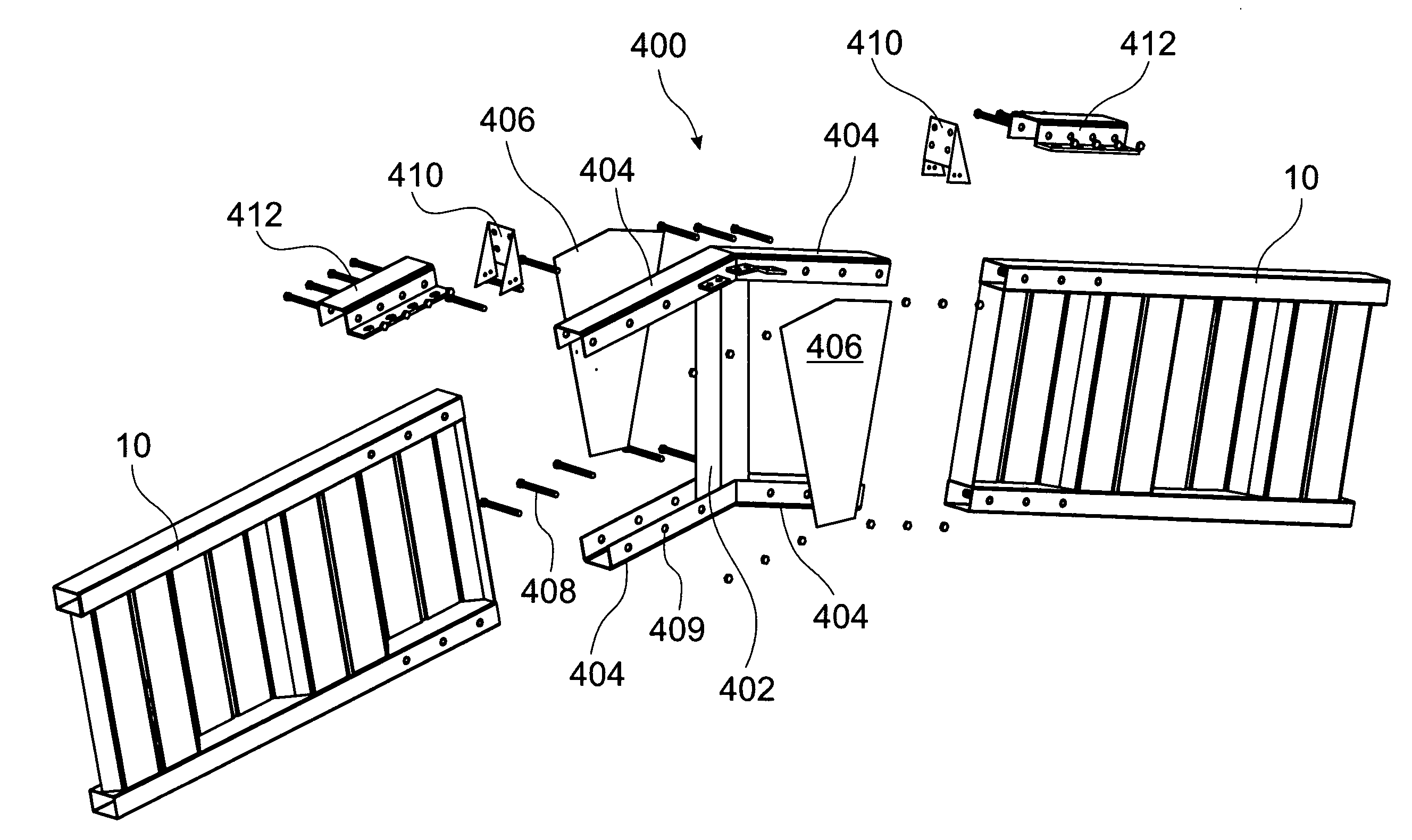
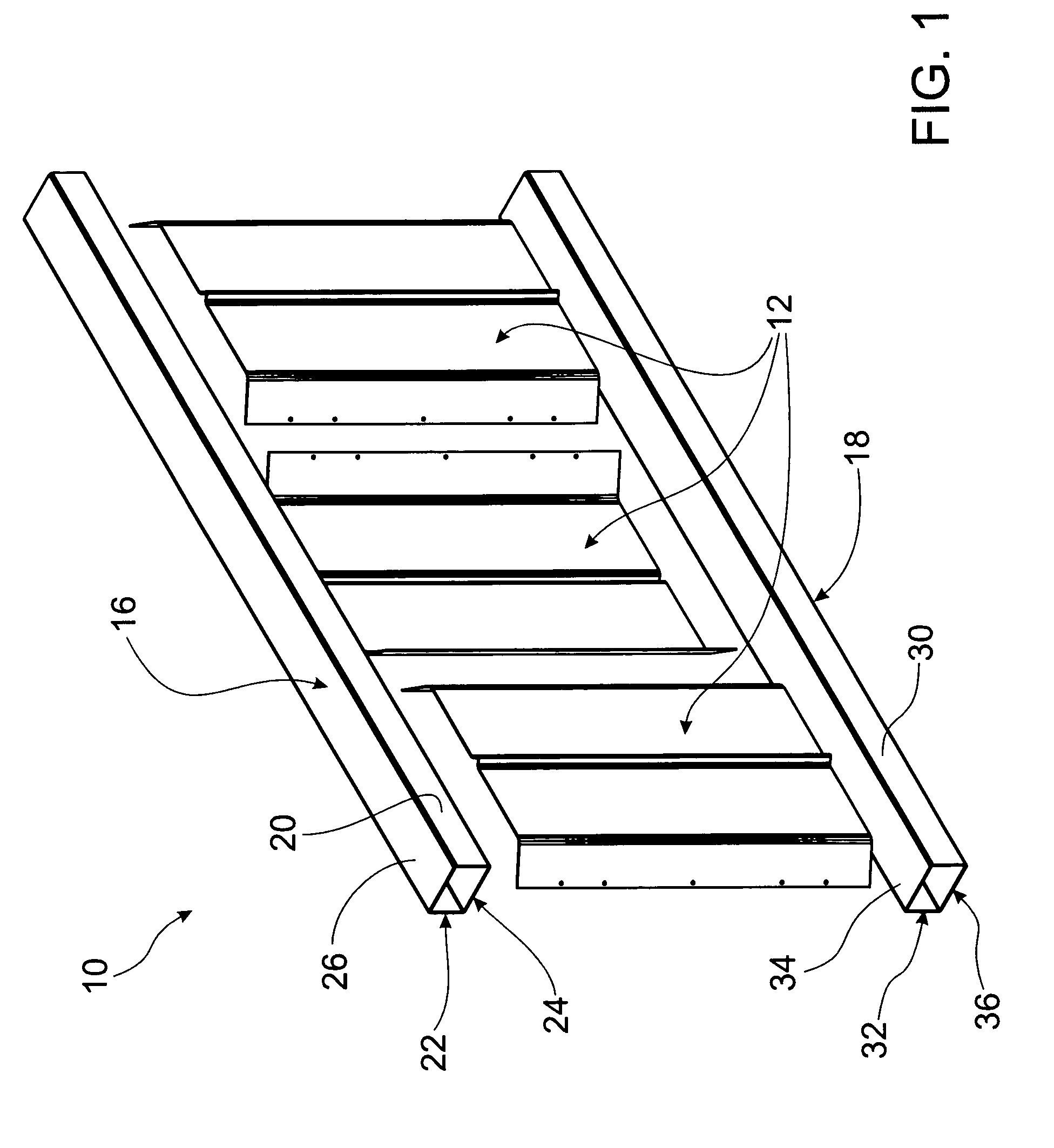
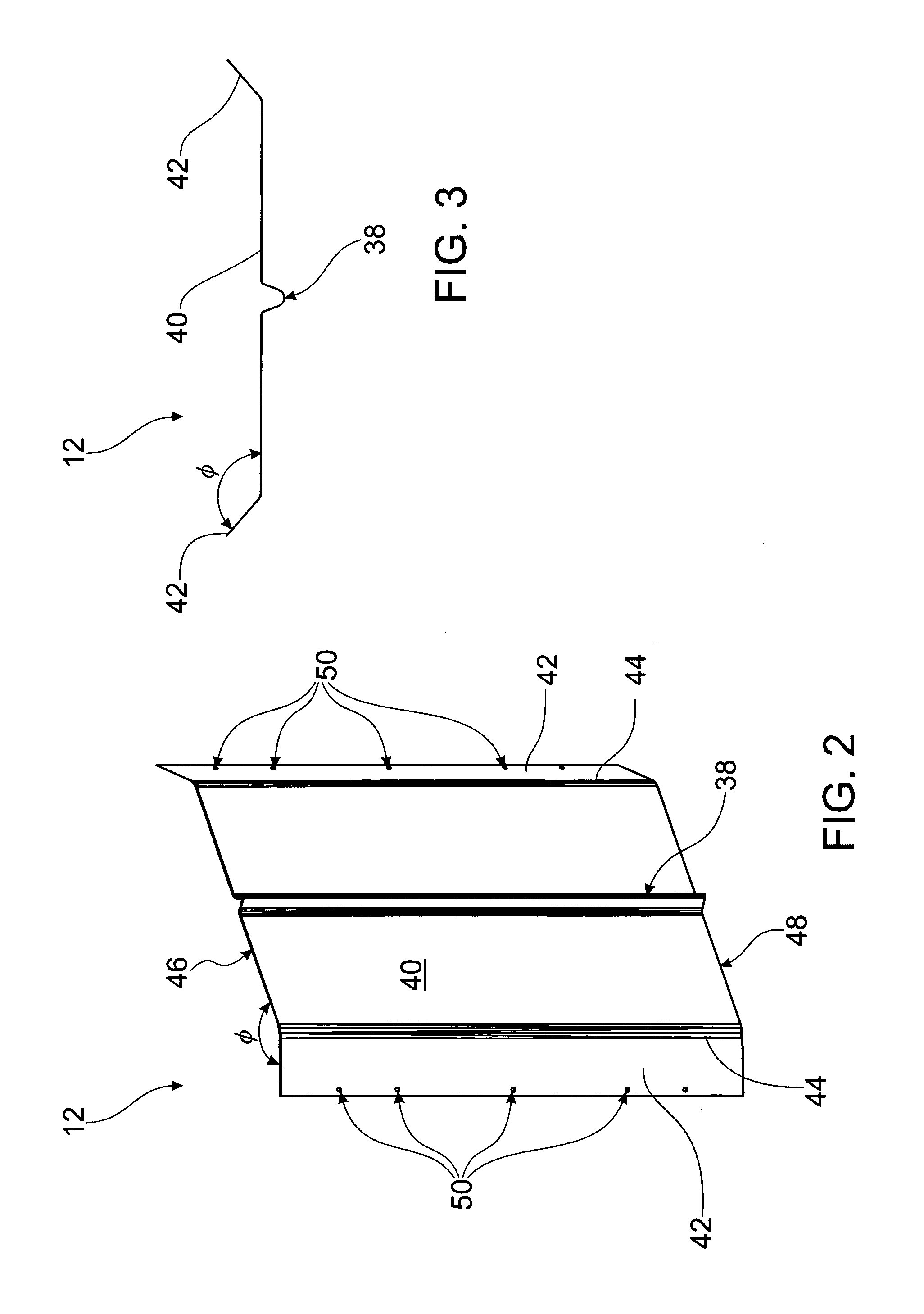
Structural building components and a method of constructing the same enable improved beams that can be constructed at a place of use. The method includes providing a first flange (16) and a second flange (18) defining a central beam axis (55). A number of separately formed web sections (12) are provided, each having two convergent side walls (42) and a central wall (40) extending between converging ends of the side walls (42). The web sections (12) are arranged side by side in an alternating arrangement wherein the central walls (40) of adjacent web sections (12) are spaced substantially parallel to each other and are transversely staggered relative to the central beam axis (55). The side walls of adjacent web sections (12) are connected to one another, and the web sections (12) are connected to both the first flange (16) and second flange (18).

Description

[0001]The present invention relates generally to building components used in the building industry; in particular, although not exclusively, the invention relates to beams and building elements for the construction of buildings with roofs spanning large distances.BACKGROUND TO THE INVENTION[0002]There are many instances in building construction requiring roofs covering large areas that are not obstructed with intermediate vertical supporting members such as columns. An example is a sporting or events stadium, where unobstructed views can be sold for premium prices. Seats in stadia with obstructed views are sold much more cheaply than those with a clear view. Another example of such a building is an aircraft hangar that must be wide enough and high enough to accommodate an aircraft having a large wing span and a high tail structure. This is especially true with the advent of so called “super-jumbos” such as the Airbus A380.[0003]Various geometric shapes have been proposed in the prio...

Claims


Application Information

Patent Timeline
Patent Type & Authority Applications(United States)
IPC IPC(8): E04C3/00B21D47/01
CPCB21D47/01B21D47/04E04B2001/2415E04B2001/2463E04B2001/2472Y10T29/49634E04C2003/0413E04C2003/0417E04C2003/0434E04C2003/0452E04C3/07
Inventor GARRY, MATTHEW JOHN JOSEPH
Owner OVERFLOW LTD
Learn More