Actuator mounting assembly

a technology for mounting brackets and actuators, which is applied in the direction of valve details, valve housings, pipe elements, etc., can solve the problems of not being able to meet the stresses to which the mounting bracket is subjected in certain orientations, the typical mounting bracket b>14/b> does not work well in all possible orientations, and the conventional mounting bracket b>14/b> is not capable of enduring the stresses of certain orientations, etc., and achiev

Inactive Publication Date: 2011-05-19
GGOSCO ENG
View PDF7 Cites 195 Cited by
  • Summary
  • Abstract
  • Description
  • Claims
  • Application Information

AI Technical Summary

Benefits of technology

[0009]In another of its aspects, the invention provides a mounting bracket for locating an actuator in a predetermined position relative to a valve at least partially controlled by the actuator. The mounting bracket includes a body element and three or more arms attached to the

Problems solved by technology

In particular, the typical mounting bracket 14 does not work well in all possible orientations relative to the horizontal and/or the vertical.
However, and as illustrated in FIG. 1B, the conventional mounting bracket 14 is not capable of withstanding the stresses to which it is subjected in certain orientations.
The consequences can be serious, a

Method used


Image

  • Actuator mounting assembly
  • Actuator mounting assembly
  • Actuator mounting assembly

Examples


Embodiment Construction

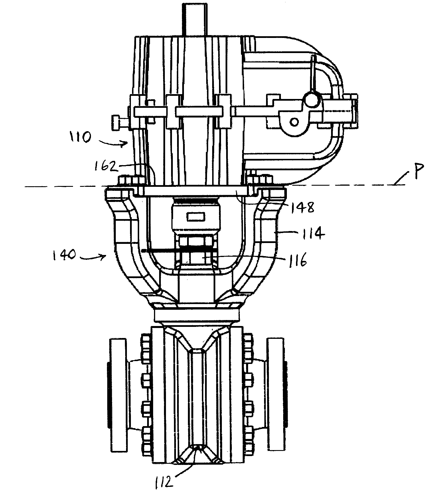
[0024]Reference is first made to FIGS. 2A-3C to describe an embodiment of a valve assembly in accordance with the invention indicated generally by the numeral 140. As can be seen in FIGS. 2A-2C, the valve assembly 140 includes a valve 112 with a valve stem 116 extending therefrom and an actuator 110 for controlling the valve 112. Preferably, the actuator 110 is connected to the valve stem 116. It is also preferred that the valve assembly 140 includes a mounting bracket 114 for supporting the actuator 110 in a predetermined position relative to the valve 112, as will be described. The mounting bracket 114 preferably includes three or more arms 142, 144, 146 (FIG. 3A) defining a plane (identified as “P” in FIGS. 2A-2C) on which the actuator 110 is located to maintain the actuator 110 in the predetermined position.

[0025]The mounting bracket 114 is illustrated in FIGS. 4A-4C. As can be seen, for instance, in FIG. 4B, the three arms 142, 144, 146 preferably are positioned substantially r...


PUM


Abstract

A mounting bracket for locating an actuator in a predetermined position relative to a valve at least partially controlled by the actuator. The mounting bracket includes a body element and three or more arms attached to the body element. Each arm extends between an inner end attached to the body element and an outer end distal to the body element, the outer ends of said at least three arms being positioned to define a plane on which the actuator is locatable, to maintain the actuator in the predetermined position.

Description

FIELD OF THE INVENTION[0001]The present invention is a mounting bracket for an actuator controlling a valve.BACKGROUND OF THE INVENTION[0002]An actuator mounting bracket, for locating an actuator relative to a valve, is well known in the art. A typical actuator mounting bracket of the prior art is illustrated in FIGS. 1A and 1B. (As will be described, the balance of the drawings illustrate the present invention). As is well known in the art, an actuator 10 for a valve 12 is required to be supported by an actuator mounting bracket 14, so that the actuator 10 may be securely attached to a valve stem 16 of the valve 12. The known bracket 14 supports the actuator 10 in a predetermined location relative to the valve 12. Because the actuator 10 acts upon the valve stem 16 to cause the valve 12 to function as required, the actuator mounting bracket 14 is required to maintain the actuator 10 in the predetermined location relative to the valve 12.[0003]In FIGS. 1A and 1B, the typical actuato...

Claims


Application Information

Patent Timeline
IPC IPC(8): F16K51/00
CPCF16K31/04F16K27/00Y10T137/6089
Inventor GOSLING, THOMAS M.ROSADA, ALESANDRO
Owner GGOSCO ENG
Why Eureka
Try Eureka