Heat-dissipating device

Inactive Publication Date: 2011-05-19
SUNONWEALTH ELECTRIC MACHINE IND
View PDF17 Cites 7 Cited by
  • Summary
  • Abstract
  • Description
  • Claims
  • Application Information

AI Technical Summary

Benefits of technology

[0008]The primary objective of the present invention is to provide

Problems solved by technology

Furthermore, dust is liable to accumulate at specific area such as the compartment 911, the first heat-dissipating fan 92 and the second heat-dissipating fan 93, and thus adversely affects the heat-dissipating effect.
Further, the heat-diss

Method used


Image

  • Heat-dissipating device
  • Heat-dissipating device
  • Heat-dissipating device

Examples


Embodiment Construction

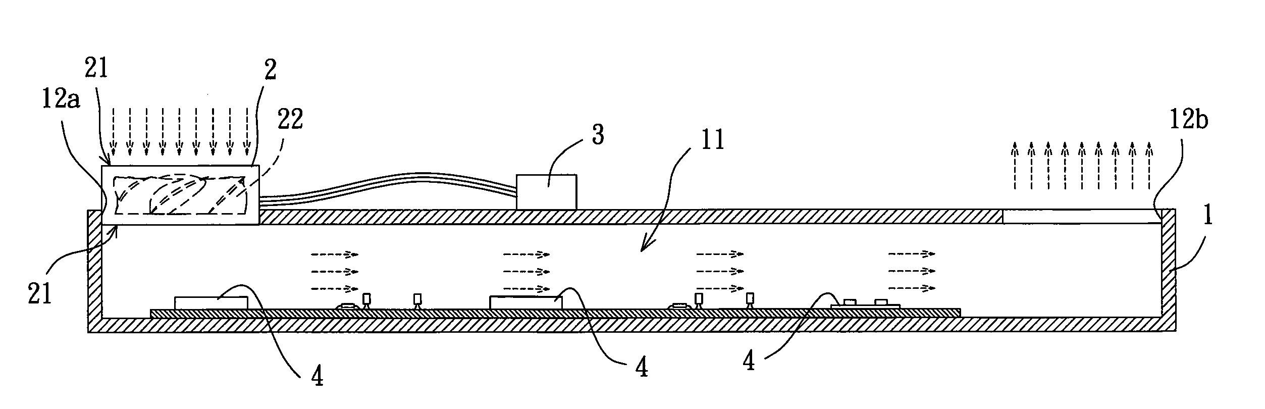
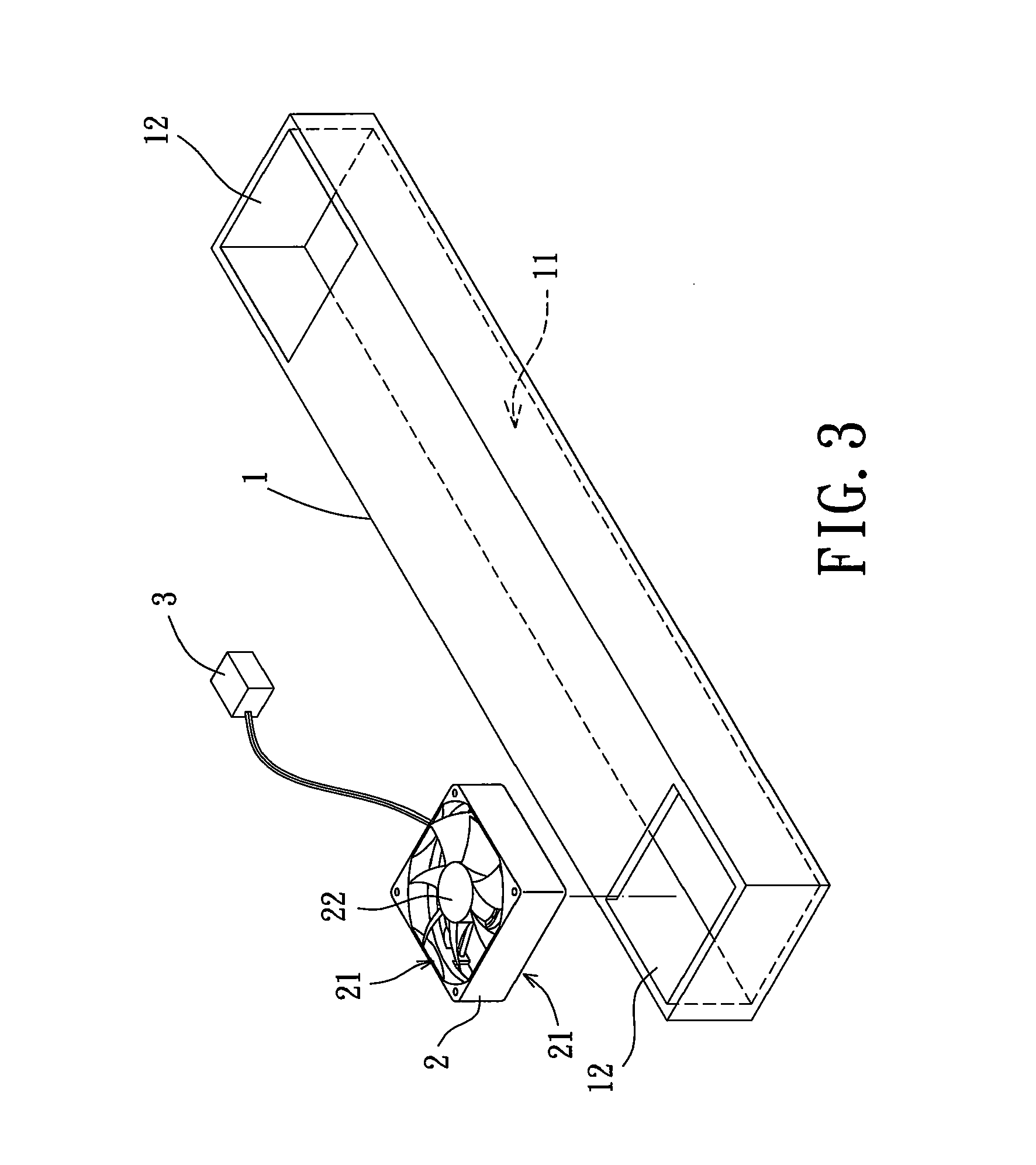
[0024]A heat-dissipating device according to the preferred teachings of the present invention is shown in FIG. 3. The heat-dissipating device includes a heat-dissipating member 1, at least one heat-dissipating fan 2, and a rotation control unit 3 adopted for control over rotating direction of the said at least one heat-dissipating fan 2.

[0025]The heat-dissipating member 1 can be integrated with an electronic product having at least one electronic element. The heat-dissipating member 1 is a hollow casting and preferably made of heat-conducting material, especially of material with high thermal conductivity. The heat-dissipating member 1 has an airflow chamber 11 inside and includes a plurality of air-guiding holes 12 in communication with the airflow chamber 11.

[0026]The at least one heat-dissipating fan 2 can be of blower type or axial flow type. In the preferred form shown in FIG. 3, the heat-dissipating device includes one heat-dissipating fan 2 of axial type. Furthermore, the hea...


PUM


Abstract

A heat-dissipating device comprises a heat-dissipating member, at least one heat-dissipating fan, and a rotation control unit. The heat-dissipating member has an airflow chamber inside and includes a plurality of air-guiding holes in communication with the airflow chamber. Each of the at least one heat-dissipating fan has two air-guiding portions, wherein one of the air-guiding portions is aligned with one of the air-guiding holes of the heat-dissipating member. The rotation control unit communicates with and controls the at least one heat-dissipating fan. Accordingly, the heat-dissipating device with a dust auto-removing function can provide a balanced heat-dissipating effect.

Description

BACKGROUND OF THE INVENTION[0001]1. Field of the Invention[0002]The present invention relates to a heat-dissipating device and, more particularly, to a heat-dissipating device capable of integrating with a plurality of heat sources in various electronic products to provide heat-dissipating function.[0003]2. Description of the Related Art[0004]During the operation of electronic products such as lamps, backlighted modules, liquid crystal display (LCD), and computers etc., heat is generated easily. Therefore, heat-dissipating devices are widely utilized to maintain normal operation and lifetime of electronic products.[0005]Furthermore, plural electronic elements of electronic products such as motherboards, microprocessors or chips of computers must be put together in a heat-dissipating member of heat-dissipating devices with plural heat-dissipating fans for heat-dissipating purpose.[0006]FIGS. 1 and 2 shows a conventional heat-dissipating device including a heat-dissipating member 91 a...

Claims


Application Information

Patent Timeline
IPC IPC(8): F28D21/00
CPCH01L23/467H05K7/2019H05K7/20209H01L2924/0002H01L2924/00
Inventor HORNG, ALEXMIYAHARA, MASAHARU
Owner SUNONWEALTH ELECTRIC MACHINE IND
Why Eureka
Try Eureka