Tank type high-pressure vacuum circuit breaker

A vacuum circuit breaker and high-voltage technology, which is applied to high-voltage air circuit breakers, high-voltage/high-current switches, circuits, etc., can solve the problems of high pressure bearing, complicated manufacturing process, and increased manufacturing difficulty of vacuum interrupters. , to achieve the effect of reducing the difficulty of manufacturing

Active Publication Date: 2014-03-26
SHENYANG HUADE HIGH TECH ELECTRIC CO LTD
View PDF5 Cites 3 Cited by
  • Summary
  • Abstract
  • Description
  • Claims
  • Application Information

AI Technical Summary

Problems solved by technology

In the prior art, such as an outdoor high-voltage vacuum circuit breaker disclosed in the patent application No. 03133431.8, it does not use sulfur hexafluoride gas as the insulating gas, but the technical solution it adopts is to fill the outside of the interrupter with a A liquid silicone rubber insulating medium, which forms a solid silicone rubber insulator after cooling. This silicone rubber insulator is solidly sealed with the arc extinguishing chamber, and the manufacturing process is complicated. Especially when the arc extinguishing chamber fails, it is impossible to replace the arc extinguishing chamber alone.
Another example is a high-voltage vacuum circuit breaker produced by Japan AE Pawa Co., Ltd., which does not use sulfur hexafluoride gas as an insulating gas, but the technical solution it adopts is to install the vacuum interrupter directly on the high-pressure circuit breaker. In the insulating gas, the vacuum interrupter is directly in the high-pressure gas, so the vacuum interrupter is under high pressure, which increases the difficulty of manufacturing the vacuum interrupter

Method used


Image

  • Tank type high-pressure vacuum circuit breaker
  • Tank type high-pressure vacuum circuit breaker
  • Tank type high-pressure vacuum circuit breaker

Examples


Embodiment Construction

[0024] Provide the specific embodiment of the utility model below in conjunction with accompanying drawing.

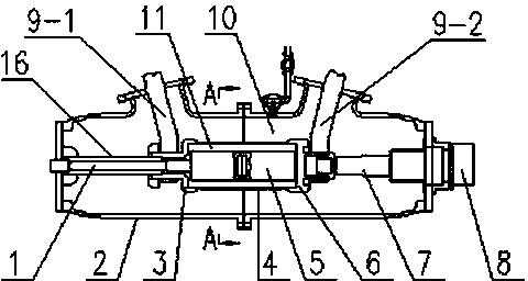
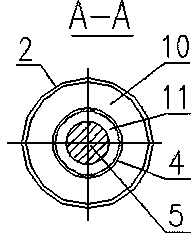
[0025] Such as figure 1 with figure 2 As shown, the present invention includes a vacuum interrupter 5, and a large insulating cylinder 4 made of epoxy resin is installed outside the vacuum interrupter 5, and the left and right shielding electrodes 3 and 3 are respectively installed at the left and right ends of the large insulating cylinder 4. 6. A small insulating cylinder 16 is installed on the left end of the left shielding electrode 3, and the cavity between the vacuum interrupter 5 and the large insulating cylinder 4 and the cavity between the small insulating cylinder 16 and the operating insulating rod 1 are connected to form a sealed low-voltage Gas compartment 11, the tank body 2 is installed outside the large insulating cylinder 4 and the small insulating cylinder 16, the cavity between the large insulating cylinder 4 and the small insulating cylinder 16 an...


PUM


Abstract

A tank type high-pressure vacuum circuit breaker solves the problems that a structure integrally and solidly sealing a silicon rubber insulator with an arc extinguish chamber is complex in manufacturing process and incapable of allowing the arc extinguish chamber to be replaced independently, and the vacuum arc extinguish chamber directly mounted in high-pressure insulating gas bears high pressure. The tank type high-pressure vacuum circuit breaker is characterized in that a cavity between a vacuum arc extinguish chamber and a large insulating cylinder and a cavity between a small insulating cylinder and an operational insulating rod are communicated with each other to form a closed low-pressure gas compartment filled with 0-0.1MPa dried air or nitrogen, and a cavity between the large insulating cylinder and a tank and a cavity between the small insulating cylinder and the tank form a closed high-pressure gas compartment filled with 0.15-0.6MPa dried air or nitrogen. The tank type high-pressure vacuum circuit breaker has the advantages that the vacuum arc extinguish chamber is operated in the low-pressure gas compartment so as to be protected effectively, and the high-pressure gas compartment guarantees insulating performance of the circuit breaker, so that only the vacuum arc extinguish chamber needs to be replaced singly if the vacuum arc extinguish chamber fails.

Description

technical field [0001] The invention belongs to the technical field of high-voltage electrical appliances, in particular to a tank-type high-voltage vacuum circuit breaker which is insulated by dry air or nitrogen for high-voltage systems. Background technique [0002] Most of the existing high-voltage circuit breakers use sulfur hexafluoride as the electrical insulation and circuit breaking medium, but the large amount of sulfur hexafluoride will pollute the environment. Based on the above reasons, the breaking circuit using vacuum breaking technology has gradually been implemented in the high voltage field. In the prior art, such as an outdoor high-voltage vacuum circuit breaker disclosed in the patent application No. 03133431.8, it does not use sulfur hexafluoride gas as the insulating gas, but the technical solution it adopts is to fill the outside of the interrupter with a A liquid silicone rubber insulating medium, which forms a solid silicone rubber insulator after c...

Claims


Application Information

Patent Timeline
Patent Type & Authority Patents(China)
IPC IPC(8): H01H33/66
Inventor 国世峥张交锁廖汉张军
Owner SHENYANG HUADE HIGH TECH ELECTRIC CO LTD
Why Eureka
Try Eureka