Self-powered detection device with a non-volatile memory

a detection device and non-volatile memory technology, applied in the direction of generator/motor, alarm lock, automatic control, etc., can solve the problems of limited lifetime of the device, inability to detect and record an event, and inability to operate the device, so as to achieve efficient reading operation and efficient reset operation

Active Publication Date: 2011-05-19
EM MICROELECTRONIC-MARIN
View PDF11 Cites 13 Cited by
  • Summary
  • Abstract
  • Description
  • Claims
  • Application Information

AI Technical Summary

Benefits of technology

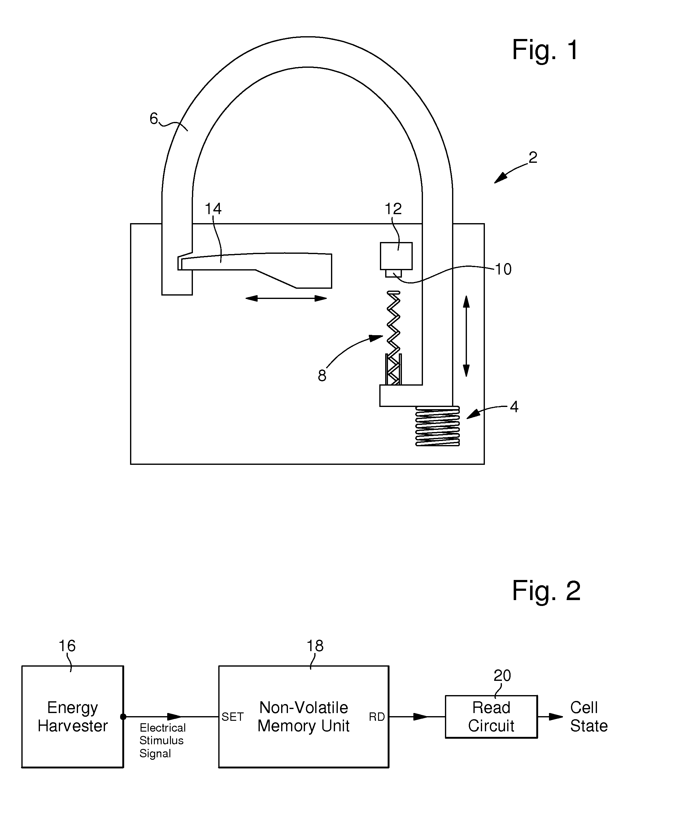
[0008]An object of the invention is to provide a self-powered detection device comprising at least a non-volatile memory cell and a sensor which is activated by a physical or chemical action or phenomenon, in particular a tamper event, and which needs only a small amount of electrical energy for setting the non-volatile memory in a secure way, this small amount of electrical energy being provided by the sensor when it de

Problems solved by technology

Without such a power source or if the power source is OFF or if the energy stored in the battery becomes too low, this device will not be functional, i.e., it will be incapable of detecting and recording an event.
Furthermore, in the case of an internal power source like a battery, such a device will have a limited lifetime or the internal power source will have to be changed after a certain time period.
This causes a security problem first because there is a risk that the detection device becomes no longer functional when an interruption of the power supply occurs, and secondly because a perpetrator could cause an interruption of the power source, stopping the electrical supply of the detection

Method used


Image

  • Self-powered detection device with a non-volatile memory
  • Self-powered detection device with a non-volatile memory
  • Self-powered detection device with a non-volatile memory

Examples


first embodiment

[0096]FIG. 9 shows such a NVM unit with a NVM cell 66 having only two terminals (2-terminal NVM Cell). In the detection mode, the voltage stimulus signal resulting from an electrical stimulus pulse generated by the sensor is applied through input SET to input A of the 2-terminal NVM Cell simultaneous with 0V (GND) on input SET * being applied to input B, as already explained. The subcircuit 68‘Isolation Crt A’ isolates SET * from output RD during a set operation (stimulus pulse applied in the detection mode) as well as during a reset operation (reset mode). To read the cell (read mode), SET is driven to 0V by Clamp B when no electrical stimulus pulse is present and thus the switch 60 (FIG. 6) is OFF, REN is driven high, and input IN is connected to output OUT to allow current to flow through subcircuit 68. To reset the cell, SET * is driven high while SET is at 0V. For the read mode and the reset mode, the switch circuit 58 is essential in order to disconnect SET * from GND / VSS.

[009...

second embodiment

[0105]FIG. 12 is a diagram of the NVM unit 52 of FIG. 6 with a NVFET cell 72, where the stimulus pulse is applied to the control gate G of the NVFET. This NVFET further comprises two diffusions defining two inputs 1 and 2. During the set operation (detection mode), the stimulus pulse is routed via input SET to the Gate G of the NVFET cell. At the same time, input SET * is driven low by switch 60 (FIG. 6), which in turn drives input 1 of the NVFET low. Subcircuit 68‘Isolation Crt A’ isolates SET * from RD except during a read operation (read mode). Electrons are stored in the charge storage material causing the threshold voltage of NVFET to be high and current low during a read operation.

[0106]During a reset operation (reset mode), SET * is driven high causing input 1 of NVFET 72 to be driven high. At the same time, SET is driven low by subcircuit 64‘Clamp B’ (FIGS. 7 & 8) driving input G low and thus the switch 60 (FIG. 6) is OFF. Electrons tunnel out of the charge storage material ...

third embodiment

[0107]FIG. 13 is a diagram of the NVM unit 52 of FIG. 6 with a NVFET cell 74, where a stimulus pulse is applied to one diffusion (Input 1) of the NVFET and where the read circuit senses, i.e. the read occurs, at the same diffusion. During the set operation (detection mode), the stimulus pulse is routed through the subcircuit 76‘Isolation Crt B’ to input 1 of NVFET 74. At the same time, SET * is driven low by transistor T2 (switch 60 of FIG. 6), which in turn drives input G of the NVFET low. Because REN is low or high impedance (not driving) and SET is high, isolation subcircuits 68(1) and 68(2) isolate IN from OUT. Both subcircuits 68(1) and 68(2) correspond to the subcircuit 68‘Isolation Crt A’ shown in FIG. 11. The isolation subcircuit 68(2) prevents any leakage current through NVFET 74 that may degrade the level of the stimulus pulse routed to the diffusion. The isolation subcircuit 68(1) isolates RD from input 1 of the NVFET also to prevent degradation of the stimulus pulse rout...


PUM


Abstract

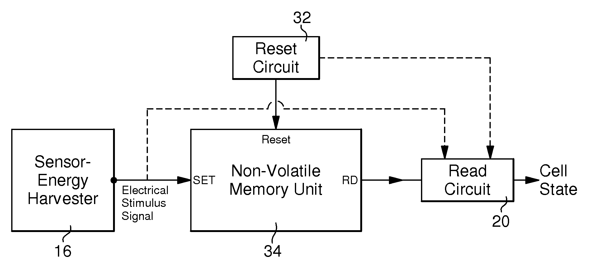
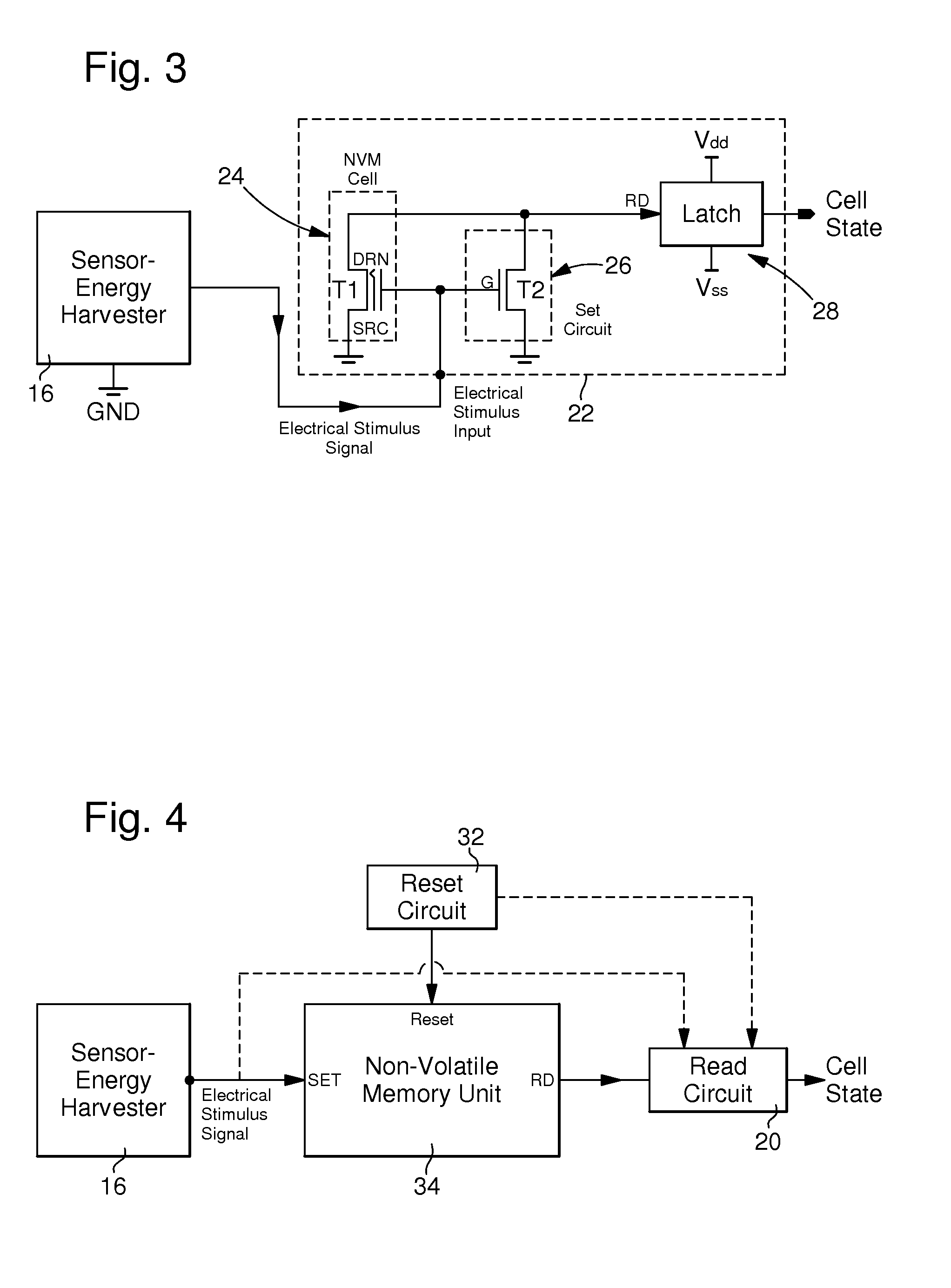
The self-powered detection device comprises a Non-Volatile Memory (NVM) unit (52) formed at least by a NVM cell and a sensor which is activated by a physical or chemical action or phenomenon, this sensor forming an energy harvester that transforms energy from said physical or chemical action or phenomenon into an electrical stimulus pulse, said NVM unit being arranged for storing in said NVM cell, by using the electrical power of said electrical stimulus pulse, a bit of information relative to the detection by said sensor, during a detection mode of the self-powered detection device, of at least one physical or chemical action or phenomenon applied to it with at least a given strength or intensity and resulting in a voltage stimulus signal provided between a set control terminal (SET) and a base terminal (SET *) of said NVM unit with at least a given set voltage. The self-powered detection device comprises a read circuit (56) or is arranged to be coupled to such a read circuit and further comprises a clamp circuit (54) located between the sensor and the NVM unit, this clamp circuit being arranged for passing said voltage stimulus signal on a set line connecting the sensor and the set control terminal of the NVM unit, this voltage stimulus pulse having a polarity corresponding to a set polarity of said NVM cell, and for blocking other voltage signals having approximately an amplitude corresponding to said set voltage or higher and an inverse polarity relative to the set polarity of said NVM cell, in order to avoid a possible erase of this NVM cell by such other voltage signals.

Description

FIELD OF THE INVENTION[0001]The present invention concerns a self-powered detection device which comprises a sensor, activated by a physical or chemical action or phenomenon applied on it with at least a given strength or intensity, and a non-volatile memory (NVM) for storing information relative to the detection of at least one physical or chemical action or phenomenon detected by said sensor. In particular, the present invention concerns a tamper event detection device for detecting a penetration in a protected zone or in a closed case or container.[0002]By ‘self-powered detection device’ it is understood that there is no need for an internal or external power source supplying the device for allowing its sensor to be activated and to detect a specific physical or chemical action or phenomenon. However, such a self-powered detection device can be supplied with power source for other functions in defined time periods, e.g. for reading the state of a memory or for resetting such a me...

Claims


Application Information

Patent Timeline
IPC IPC(8): H03K5/08G11C7/00H01L41/113
CPCE05B39/00E05B45/06E05B51/023E05B67/22G08B29/181E05B2047/0062E05B2047/0064G08B13/06E05B2047/0058
Inventor KAMP, DAVID A.
Owner EM MICROELECTRONIC-MARIN
Why Eureka
Try Eureka