Wireless temperature measuring system

a temperature measurement and wireless technology, applied in the field of wireless temperature measurement system, can solve the problems of field debugging, inability to facilitate remote monitoring, easy to affect infrared measurement method, etc., and achieve the effect of facilitating centralized remote monitoring, increasing the transmission distance of the rf module, and simple installation

Inactive Publication Date: 2011-05-19
WUHAN AMATE TECH +1
View PDF9 Cites 36 Cited by
  • Summary
  • Abstract
  • Description
  • Claims
  • Application Information

AI Technical Summary

Benefits of technology

[0025]Advantages of the invention include: by collecting temperature at the temperature detection point by the wireless temperature sensor, and performing cyclic-interleave and error-correction coding on the temperature signal, transmission distance of the RF module is increased; one communication terminal is capable of managing up to hundreds of wireless temperature sensor, centralized remote monitoring can be facilitated, no in-situ cable laying is required, installation is simple, extension is convenient, and the invention is not affected by sunshine or illumination.

Problems solved by technology

However, there are several problems with the conventional methods: firstly, the field bus measuring method requires in-situ cable laying, which features complex installation and inconvenient extension, and remote monitoring cannot be facilitated; secondly, the infrared measuring method is easily affected by sunshine or illumination and requires field debugging, and remote monitoring cannot be facilitated.

Method used


Image

  • Wireless temperature measuring system
  • Wireless temperature measuring system
  • Wireless temperature measuring system

Examples


Embodiment Construction

[0033]Further description will be given below in conjunction with accompanying drawings and specific embodiments.

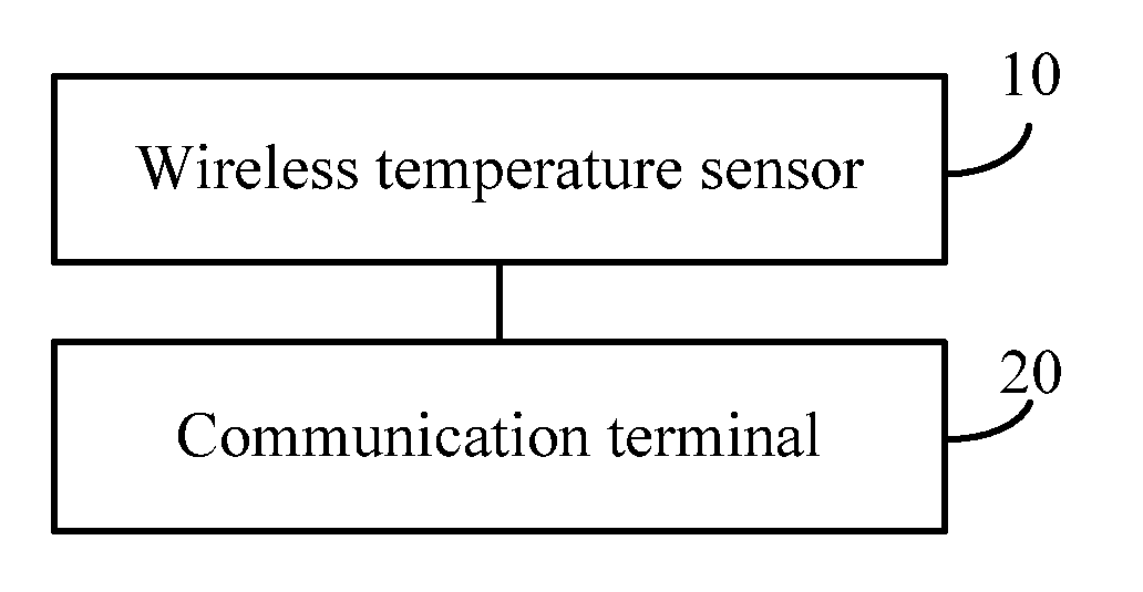
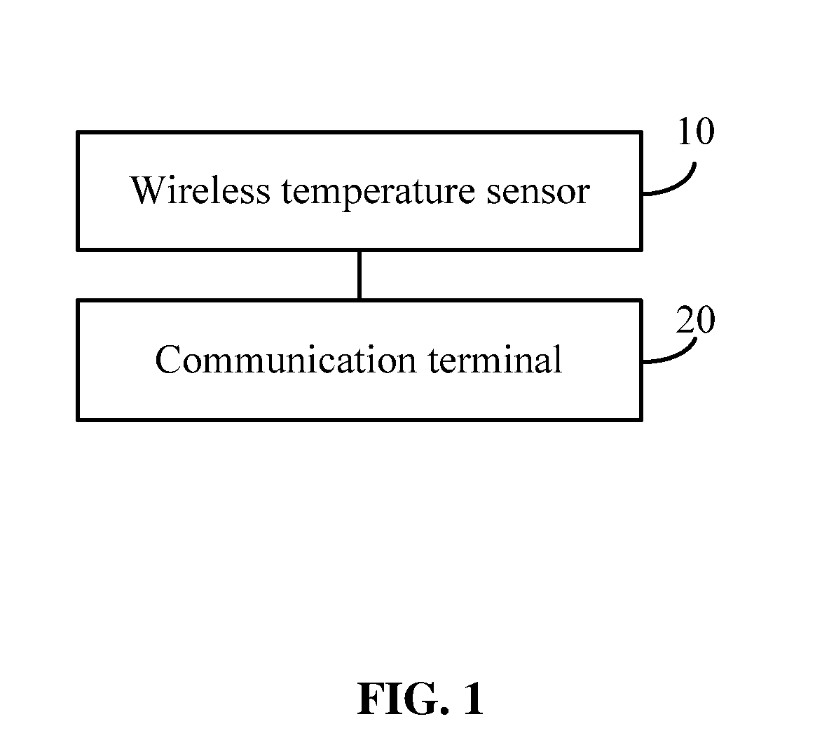
[0034]As shown in FIG. 1, a wireless temperature measuring system comprises multiple wireless temperature sensors 10, and multiple communication terminals 20. The wireless temperature sensors 10 communicate with the communication terminals 20 via radio frequency (RF).

[0035]The wireless temperature sensor 10 operates to obtain temperature signals from a temperature detection point, to perform cyclic-interleave and error-correction coding on the temperature signals whereby obtaining coded temperature signals, and to transmit the coded temperature signals to the communication terminal 20 via RF.

[0036]The communication terminal 20 operates to receive and decode the coded temperature signals from the wireless temperature sensor 10, and to obtain decoded temperature signals.

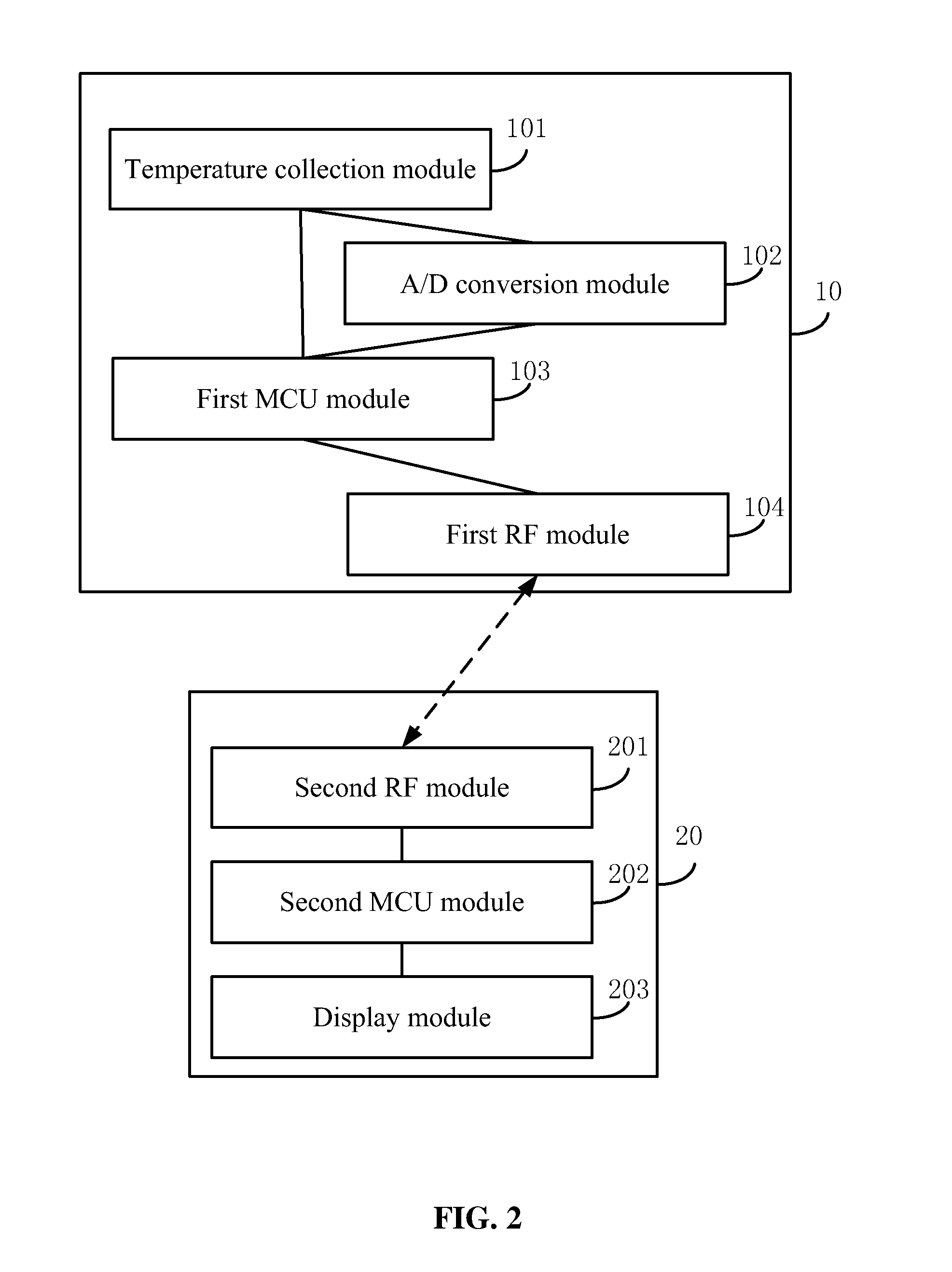
[0037]As shown in FIG. 2, the wireless temperature sensor 10 comprises a temperature collection module 10...


PUM

PropertyMeasurementUnit
frequencyaaaaaaaaaa
temperatureaaaaaaaaaa
frequencyaaaaaaaaaa

Abstract

A wireless temperature measuring system, including multiple wireless temperature sensors, and multiple communication terminals; the wireless temperature sensors communicate with the communication terminals via RF, the wireless temperature sensor operates to obtain temperature signals from a temperature detection point, to perform cyclic-interleave and error-correction coding on the temperature signals whereby obtaining coded temperature signals, and to transmit the coded temperature signals to the communication terminals via RF; the communication terminal operates to receive and decode the coded temperature signals from the wireless temperature sensor, and to obtain decoded temperature signals.

Description

CROSS-REFERENCE TO RELATED APPLICATIONS[0001]This application is a continuation of International Patent Application No. PCT / CN2010 / 076666 with an international filing date of Sep. 7, 2010, designating the United States, now pending, and further claims priority benefits to Chinese Patent Application No. 200920229807.7 filed on Nov. 16, 2009. The contents of all of the aforementioned applications, including any intervening amendments thereto, are incorporated herein by referenceBACKGROUND OF THE INVENTION[0002]1. Field of the Invention[0003]The invention relates to a wireless temperature measuring system.[0004]2. Description of the Related Art[0005]Temperature is an important measuring parameter in many fields such as industry, military, electric power and so on. Conventional methods for measuring temperature include: 1) a field bus measuring method: multiple temperature probes are disposed at each temperature detection point, a field bus is connected to a programmable logic controlle...

Claims


Application Information

Patent Timeline
Patent Type & Authority Applications(United States)
IPC IPC(8): G08B17/00G01K1/02G06F15/00G01K1/024
CPCG01K1/024H04Q2209/823H04Q2209/40H04Q9/00
Inventor ZHANG, CHANGHUAN
Owner WUHAN AMATE TECH
Why Eureka
Try Eureka