
Infrared Touch Screen

Inactive Publication Date: 2011-05-19
AMLOGIC
View PDF6 Cites 87 Cited by
  • Summary
  • Abstract
  • Description
  • Claims
  • Application Information

AI Technical Summary

Benefits of technology

[0014]An object of this invention is to provide systems for improving reliability for detecting touch events by an optical touch screen.
[0016]Yet another object of this invention is to provide methods for group scanning of paired transmitters and receivers of an optical touch screen to improve reliability for detecting touch events.
[0018]An advantage of this invention is that systems for improving reliability for detecting touch events by an optical touch screen are provided.
[0020]Yet another advantage of this invention is that methods for group scanning of paired transmitters and receivers of an optical touch screen are provided to improve reliability for detecting touch events.

Problems solved by technology

However, conventional optical touch screens are problematic in that the receivers may detect incidental beams not emitted by their paired transmitters since beams from adjacent transmitters may be detected by non-paired receivers; thus, leading to non-detection of an object on or in proximity to the touch screens.

Method used


Image

  • Infrared Touch Screen
  • Infrared Touch Screen
  • Infrared Touch Screen

Examples


Embodiment Construction

[0028]In order to aid in the understanding of the present invention, optical touch screens will be used to illustrate various embodiments of the present invention. However, it is not intended to limit the invention to optical touch screens. In fact, the invention may apply to any touch screen that uses electromagnetic (“EM”) waves (e.g., visible light beams, infrared waves, microwaves, radio waves, sonar waves, and other electromagnetic waves) for detecting touch events.

Alternating Scheme

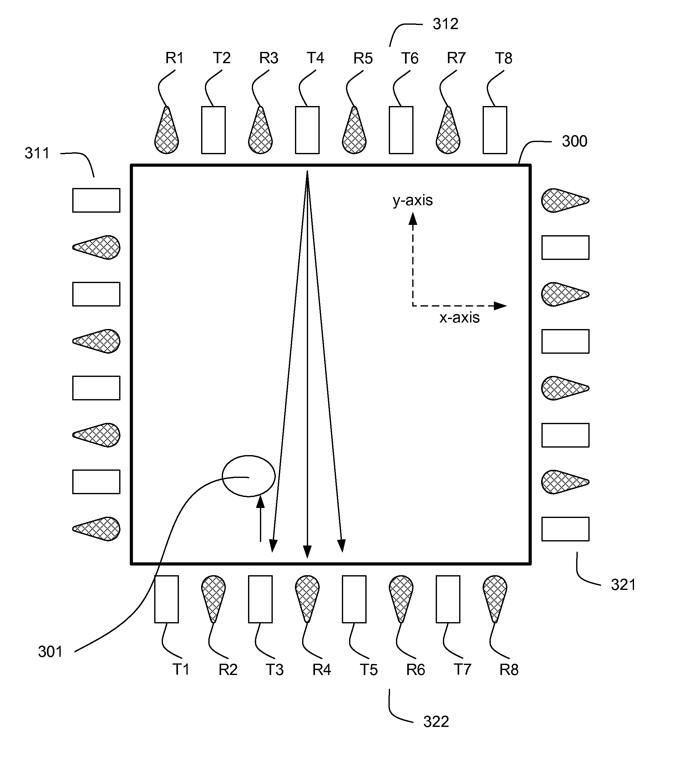
[0029]FIG. 3a illustrates a system of the present invention for detecting touch events by an optical touch screen where transmitters and receivers are positioned in alternating order on each side of a detection area of the touch screen. A touch screen can have transmitters and receivers positioned along the left side 311 of the touch screen in alternating order. The right side 321 of the touch screen also can have transmitters and receivers positioned in alternating order. For a transmitter position...


PUM


Abstract

A touch screen system comprises the following: a detection area having at least two sides; light transmitters (“LTs”) disposed on the sides; and light receivers (“LRs”) disposed on the sides, wherein the LTs and the LRs are paired where one of the LTs is paired with one of the LRs, forming transmitter-receiver pairs, wherein the transmitter-receiver pairs are positioned on the sides, where the light transmitter and the light receiver of anyone of the transmitter-receiver pairs are disposed on different ones of the sides, wherein selected ones of the transmitter-receiver pairs are partitioned into two or more groups as a function of the respective positions of the transmitter-receiver pairs along the sides, and wherein one of the groups is activated at a given time.

Description

FIELD OF INVENTION[0001]This invention relates generally to touch screens, and, more particularly, to scanning methods and systems for infrared ray (“IR”) touch screens.BACKGROUND[0002]Touch screens are used in conjunction with a variety of display devices, including cathode ray tubes (“CRTs”) and liquid crystal displays (“LCDs”), as a means of inputting information into a data processing system. When a touch screen is placed over a display or integrated into the display, the touch screen allows a user to select a displayed icon or element by touching the screen in a location corresponding to the selected icon or element.[0003]Touch screens have become common place in a variety of different applications including, for example, point-of-sale applications such as cash registers at fast-food restaurants, point-of-information applications such as department store information kiosks, ticketing applications such as airline-ticket kiosks, and other applications.[0004]There are typically fo...

Claims


Application Information

Patent Timeline
IPC IPC(8): G06F3/042
CPCG06F3/0421
Inventor XU, LIN
Owner AMLOGIC
Features
  • Generate Ideas
  • Intellectual Property
  • Life Sciences
  • Materials
  • Tech Scout
  • Unparalleled Data Quality
  • Higher Quality Content
  • 60% Fewer Hallucinations
Learn More