Rotatable positioning pivot structure and driver having the same

a technology of pivot structure and pivot rod, which is applied in the direction of casing/cabinet/drawer details, electrical apparatus, casing/cabinet/drawer details, etc., can solve the problems and affecting the use of the device. , to achieve the effect of reducing the friction force of positioning, facilitating use, and facilitating us

Inactive Publication Date: 2011-05-19
DELTA ELECTRONICS INC
View PDF1 Cites 7 Cited by
  • Summary
  • Abstract
  • Description
  • Claims
  • Application Information

AI Technical Summary

Benefits of technology

[0015]In comparison with prior art, the rotatable positioning pivot structure of the present invention is provided with the positioning shaft and the rib in the casing. Further, the cover is provided with the through trough and the elastic piece. The positioning shaft is positioned in the through trough in such a manner that the rib presses the abutting portion to cause an elastic deformation. With the elastic piece abutting the rib, the frictional force for positioning can be increased. Further, the pivot structure of the present invention is simple in construction. The cover can be assembled with the casing easily. Thus, the practicability and the convenience of the present invention can be increased.

Problems solved by technology

Since the connecting terminals of the driver have to be exposed to the outside of the box for electrical connection, the connecting terminals are still prone to be rusted by humidity or covered by dust easily.
Further, a user may touch the displayed connecting terminals carelessly to cause the breakdown of the driver.
As a result, the cover may fall on the connecting terminals unintentionally, which makes the user inconvenient in use.
Although another terminal cover having a positioning shaft is proposed, its construction is so complicated that the user cannot use it well and sometimes makes it to suffer damage carelessly.

Method used


Image

  • Rotatable positioning pivot structure and driver having the same
  • Rotatable positioning pivot structure and driver having the same
  • Rotatable positioning pivot structure and driver having the same

Examples


Embodiment Construction

[0029]The characteristics and technical contents of the present invention will be described with reference to the accompanying drawings. However, the drawings are illustrative only but not used to limit the present invention.

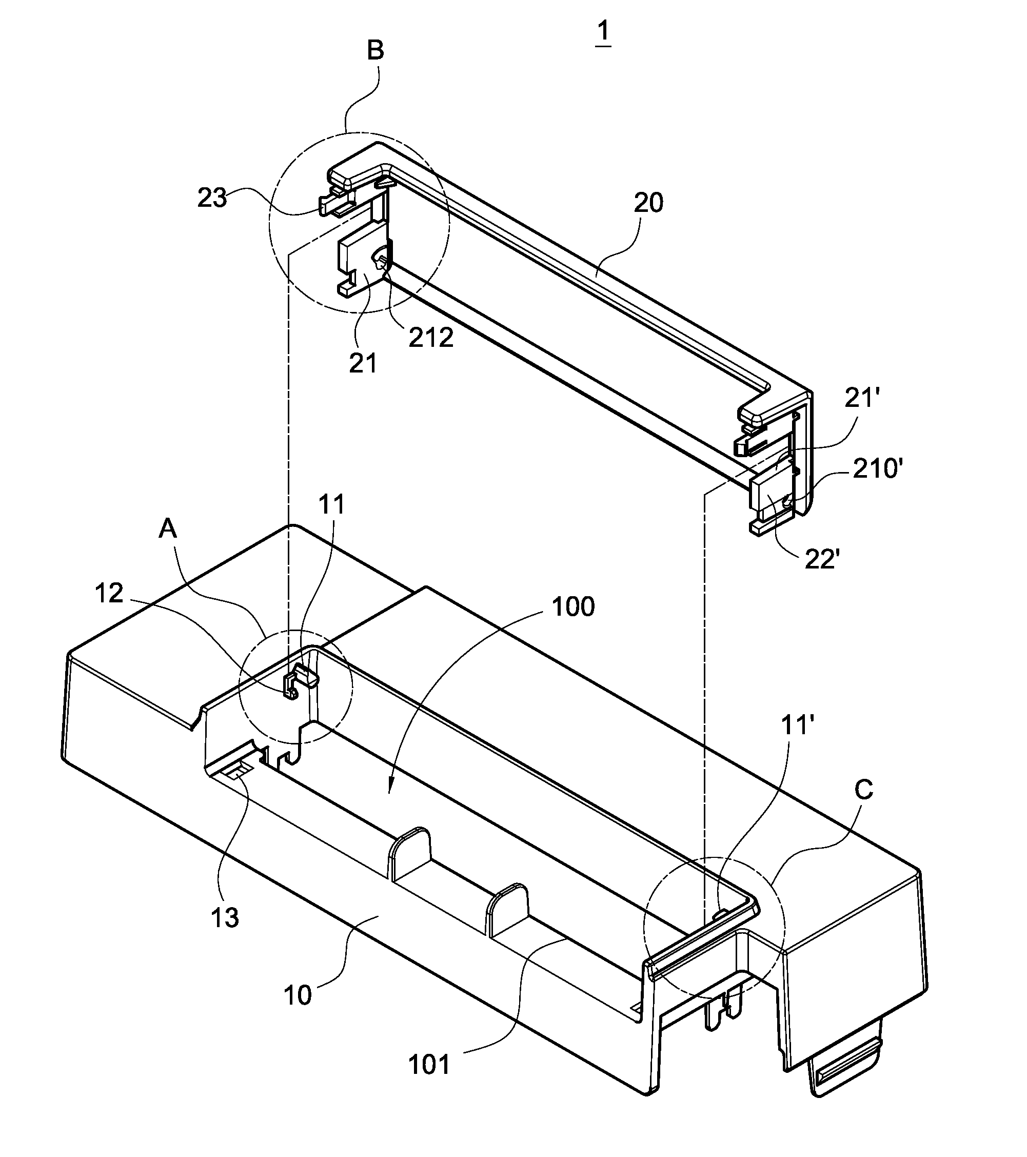
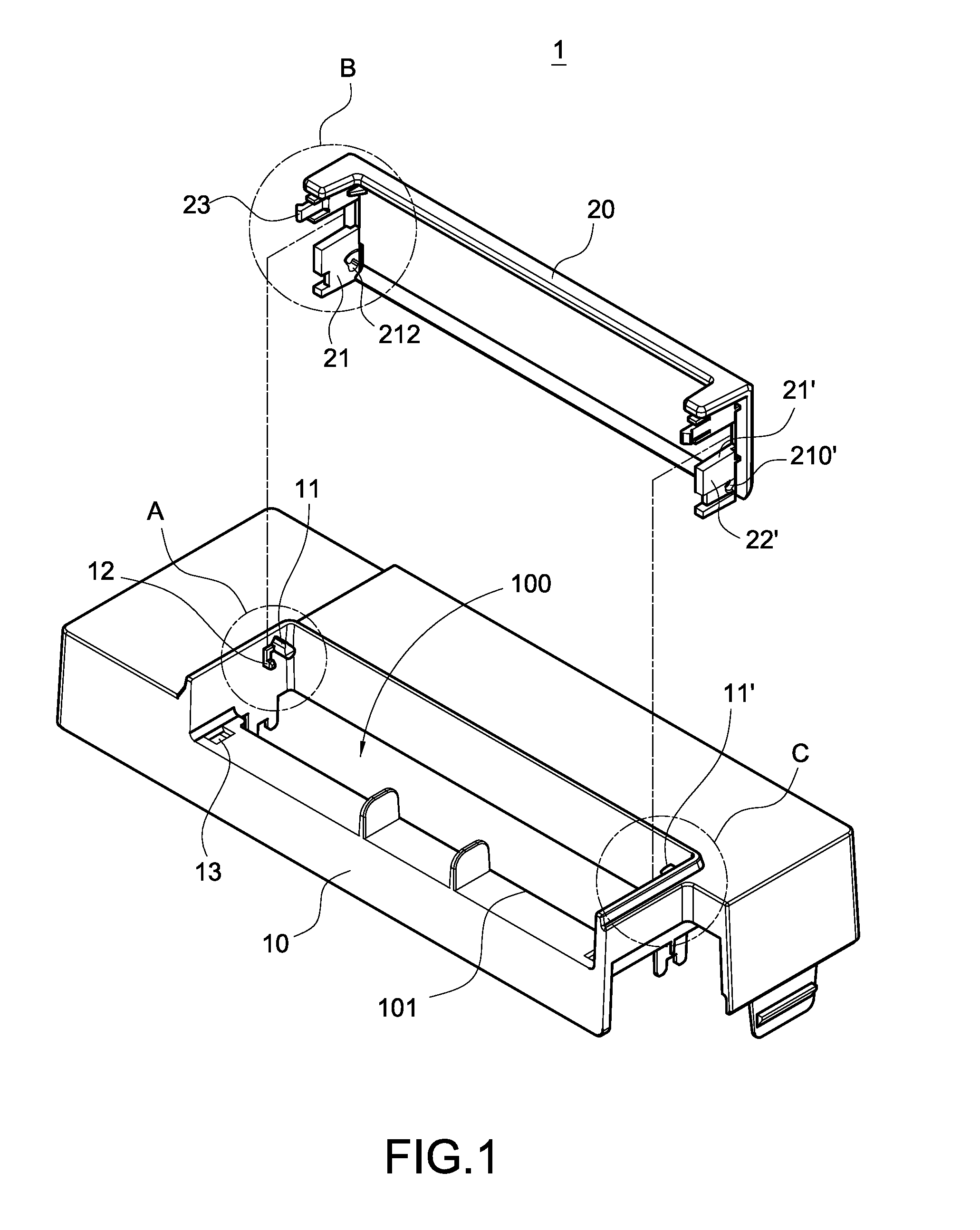
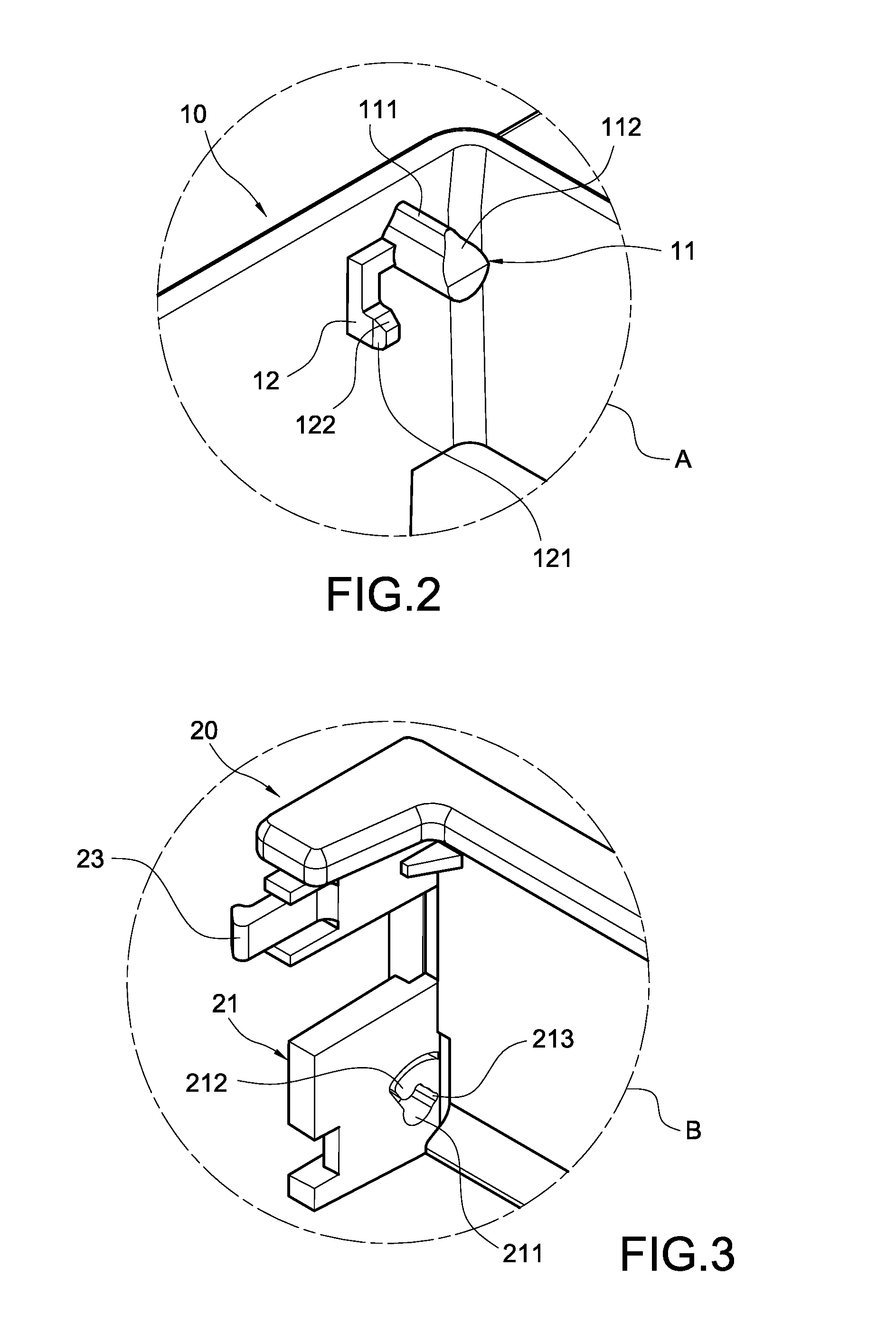
[0030]Please refer to FIGS. 1 to 6. FIG. 1 is an exploded perspective view showing the rotatable positioning pivot structure of the present invention. FIGS. 2 to 4 are enlarged views showing a portion of the present invention respectively. FIGS. 5 and 6 are assembled perspective views of the present invention. The pivot structure 1 of the present invention includes a casing 10 and a cover 20. With the pivot structure 1, the cover 20 is movably assembled with the casing 10, and the rotation of the cover 20 can be positioned easily.

[0031]Please refer to FIG. 2, which is an enlarged view showing the portion A of FIG. 1. The casing 10 is provided with an opening 101 and an accommodating space 100 in communication with the opening 101. The casing 10 is provided on on...


PUM


Abstract

In a rotatable positioning pivot structure and a driver having the pivot structure, the pivot structure includes a casing and a cover movably assembled with the casing. The casing is provided with an opening. One side of the opening is provided with a positioning shaft. The positioning shaft is provided with a positioning portion. One side of the cover is provided with an elastic piece. The elastic piece is provided with a through trough, and an elastic arm is formed in the through trough. The positioning shaft of the casing penetrates the through trough of the cover and is located inside the elastic arm. The inside of the elastic arm is provided with at least one positioning slot to be engaged with the positioning portion of the positioning shaft. With the above arrangement, the rotation of the cover can be positioned. Further, the pivot structure is arranged in the driver.

Description

BACKGROUND OF THE INVENTION[0001]1. Field of the Invention[0002]The present invention relates to a pivot structure, and in particular to a pivot structure having a positioning effect.[0003]2. Description of Prior Art[0004]Usually, a driver is used to control the operation of a motor or an electronic device, thereby achieving the required output current or rotating speed.[0005]The conventional driver has a circuit board on which control chips, resistors, capacitors and other electronic elements are arranged. The circuit board is further provided with a plurality of connecting terminals. Electric leads of the motor or the electronic device are electrically connected to the connecting terminals respectively, so that the operation of the motor or the electronic device can be controlled by the circuit board.[0006]In order to prevent the circuit board of the driver from suffering damage due to humidity or dust, the driver is usually sealed by a box. Since the connecting terminals of the d...

Claims


Application Information

Patent Timeline
Patent Type & Authority Applications(United States)
IPC IPC(8): H05K7/00
CPCH05K5/03H05K5/0239
Inventor WANG, YI-CHENTSAI, MI-TIENHUANG, MING-HUA
Owner DELTA ELECTRONICS INC
Why Eureka
Try Eureka