Mounting assisting member and lighting apparatus
- Summary
- Abstract
- Description
- Claims
- Application Information
AI Technical Summary
Benefits of technology
Problems solved by technology
Method used
Image

Examples
embodiment 1
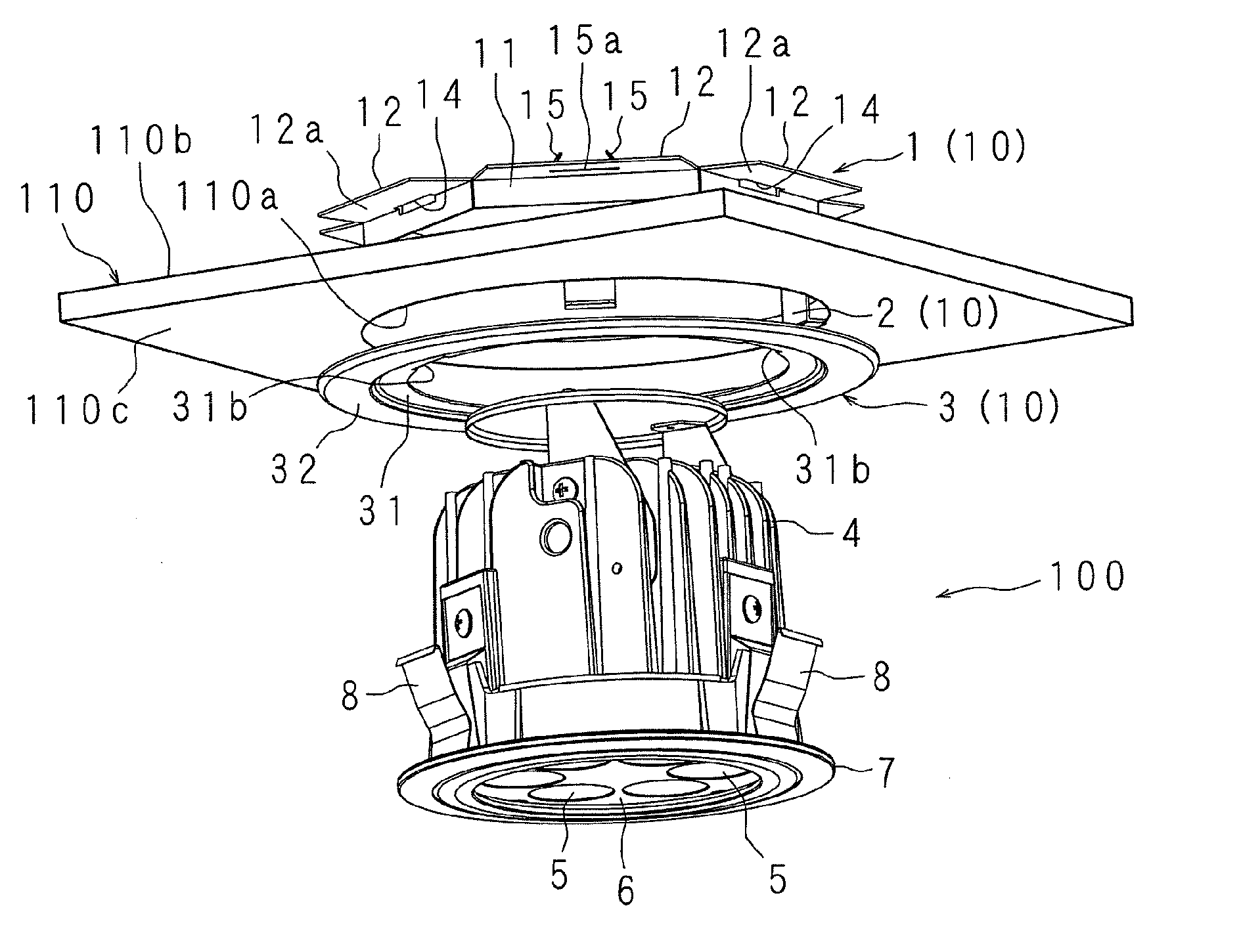
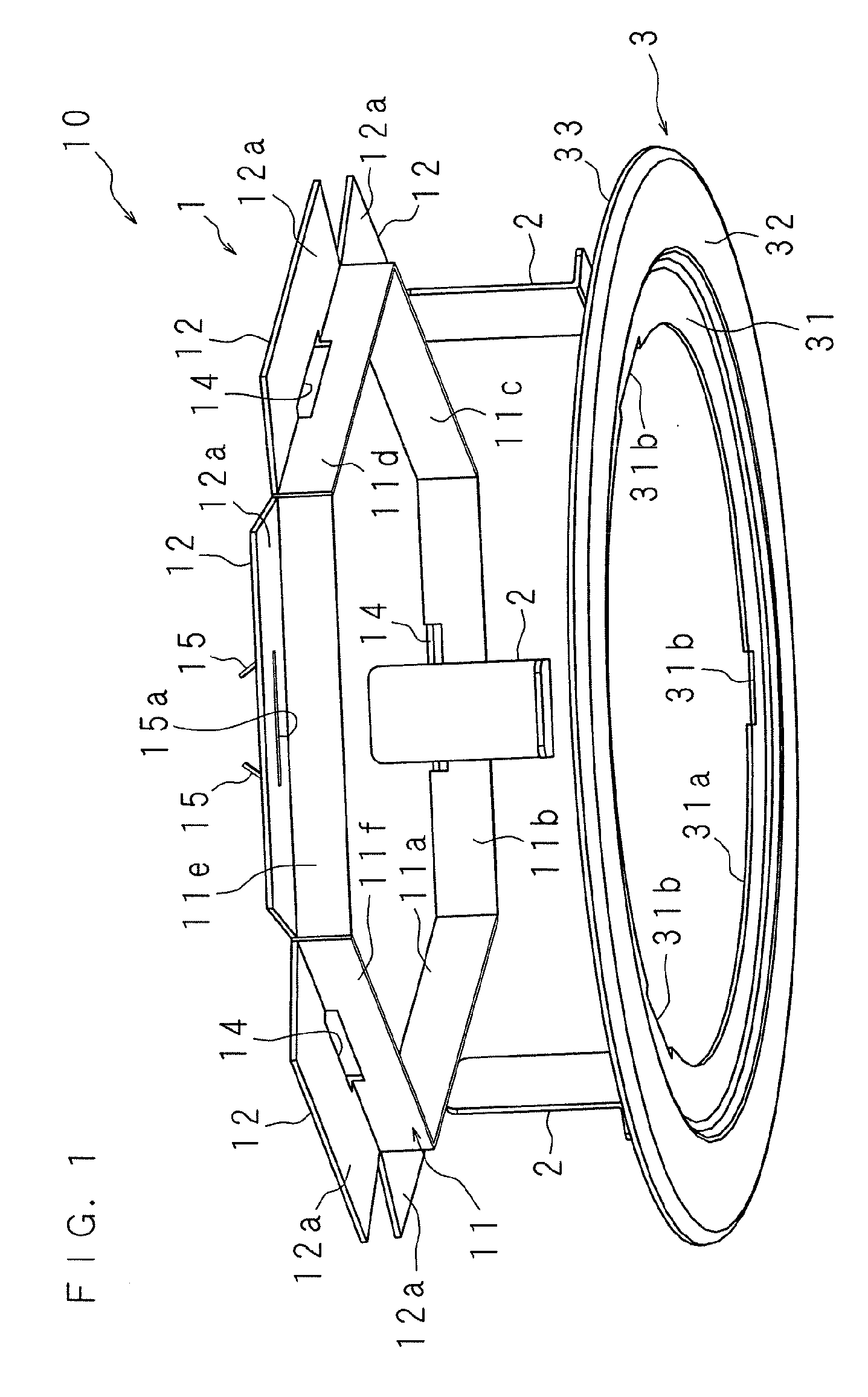
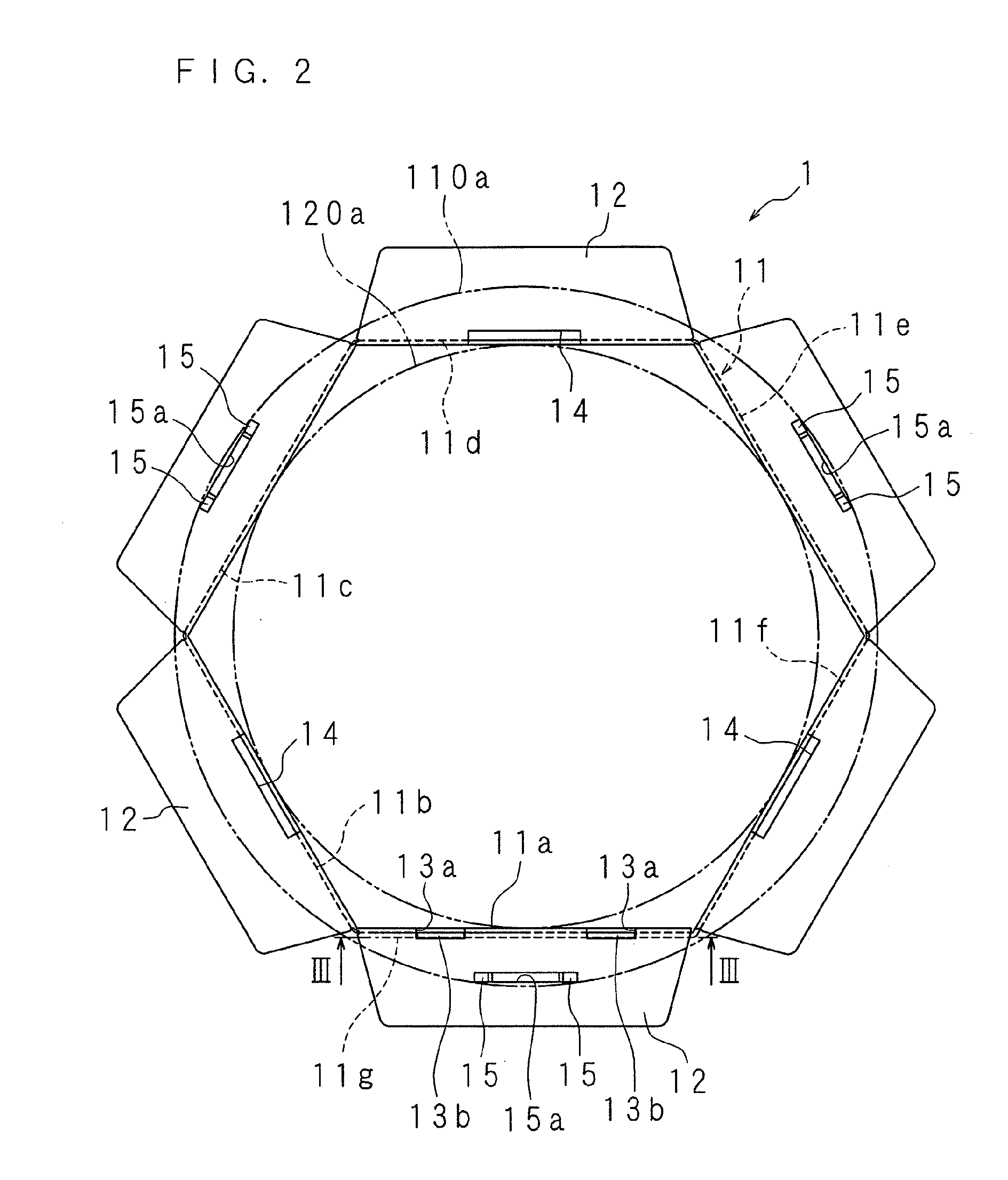
[0064]FIG. 1 is an exploded perspective view of a mounting assisting member 10 in accordance with an Embodiment 1 of the present invention. In the drawing, reference numeral 1 denotes a support frame. FIG. 2 is a schematic plan view of the support frame 1. FIG. 3 is a partly enlarged cross sectional view along a line III-III in FIG. 2. In this case, in FIG. 2, there are shown a mounting hole 110a provided in the ceiling corresponding to the mounting member and a mounting hole 120a to which the lighting apparatus main body corresponding to a mounted body should be mounted, respectively by two-dot chain lines.
[0065]The support frame 1 is provided with a hexagonal tubular base portion 11, and a plurality of (six in the drawing) support plate portions 12, 12, . . . provided in a direction which is approximately orthogonal to the base portion 11, along one side of the base portion 11, as shown in FIGS. 1 and 2.
[0066]The base portion 11 has approximately rectangular tabular seven side wal...
embodiment 2
[0111]FIG. 13 is an exploded perspective view of a mounting assisting member 20 in accordance with an Embodiment 2 of the present invention. In the drawing, reference numeral 16 denotes a support frame. FIG. 14 is a schematic plan view of the support frame 16. In this case, a mounting hole 110a provided in the mounting member is shown by a two-dot chain line in FIG. 14.
[0112]The support frame 16 is formed as a disc shape having a circular opening 16a in the center, as shown in FIG. 14. Rectangular concave portions 16b, 16b, . . . are provided in an inner peripheral edge of the support frame 16 so as to be three uniformly arranged in a peripheral direction. In this case, a leaf spring corresponding to a mounting device of a mounted body is brought into contact with the concave portions 16b, 16b, . . . .
[0113]The support frame 16 is provided with pressing pieces 15, 15, . . . corresponding to an engagement portion so as to be uniformly arranged in the peripheral direction, respectivel...
embodiment 3
[0127]The Embodiments 1 and 2 are structured such that the ceiling 110 is sandwiched by the holding device and the support frame of the mounting assisting member in order to prevent the support frame from coming off from the mounting hole 110a at a time of mounting the lighting apparatus, however, may be structured such that the ceiling 110 is sandwiched by the cover and the support frame by engaging the holding device and the support frame. A description will be given below of an example in which the latter structure is applied to the mounting assisting member having approximately the same construction as the mounting assisting member 20 in accordance with the Embodiment 2.
[0128]FIG. 18 is a schematic plan view of a support frame 18 of a mounting assisting member 30 in accordance with the present Embodiment 3. In this case, a mounting hole 110a provided in a mounting member is shown by a two-dot chain line in FIG. 18. The support frame 18 is formed as a disc shape having a circular...
PUM
 Abstract
Description
Claims
Application Information