Communication Terminal With Multiple Virtual Network Interfaces

a communication terminal and network interface technology, applied in multiplex communication, time-division multiplex, electrical equipment, etc., can solve the problems of head end that is no longer able to receive upstream signals from certain stts, unable to output enough upstream rf power to effectively communicate with the head end, and may have difficulty polling the s

Active Publication Date: 2011-05-19
TIVO CORP
View PDF2 Cites 28 Cited by
  • Summary
  • Abstract
  • Description
  • Claims
  • Application Information

AI Technical Summary

Problems solved by technology

Upgrade of subscriber network head ends to comply with the OCAP (OpenCable Application Platform) and DSG (DOCSIS Set-Top Gateway) specifications promulgated by Cable Television Laboratories, Inc. can result in some head ends that are no longer able to receive upstream signals from certain STTs.
STTs in such an environment may be unable to output enough upstream RF power to effectively communicate with the head end.
Although an STT could be configured to use an existing MoCA interface for upstream data communications routed through a cable modem, this could present other problems.
If an STT is connected to a cable modem through a router, the head end may have difficulty polling the STT.
If an STT's MoCA interface is connected directly to a cable modem, however, other devices in the home may not be able to communicate to the STT.
Although an STT could be constructed with multiple MoCA interfaces, adding hardware to implement multiple MoCA interfaces could significantly increase STT unit cost.
Networking multiple STTs through their respective MoCA interfaces also presents other challenges.
Although it is possible to create multiple physical channels in a MoCA RF frequency band, inter-channel interference can result.

Method used


Image

  • Communication Terminal With Multiple Virtual Network Interfaces
  • Communication Terminal With Multiple Virtual Network Interfaces
  • Communication Terminal With Multiple Virtual Network Interfaces

Examples


Embodiment Construction

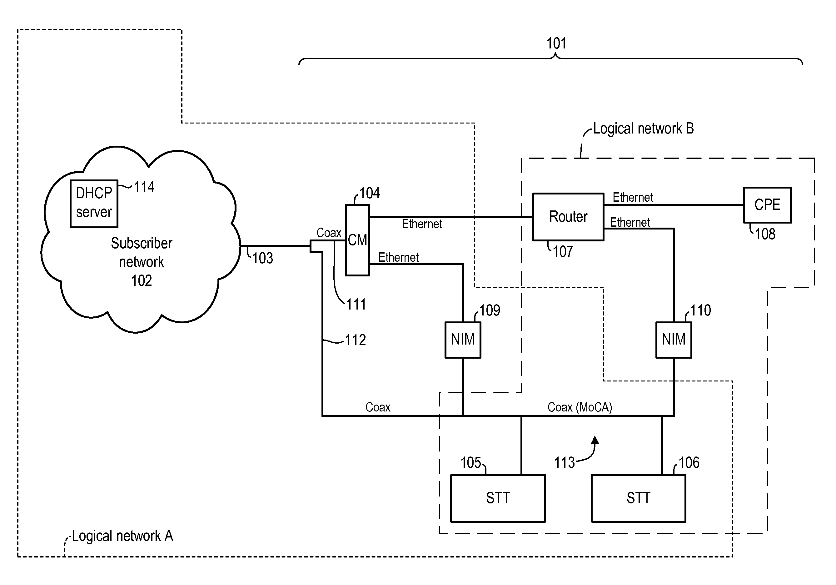
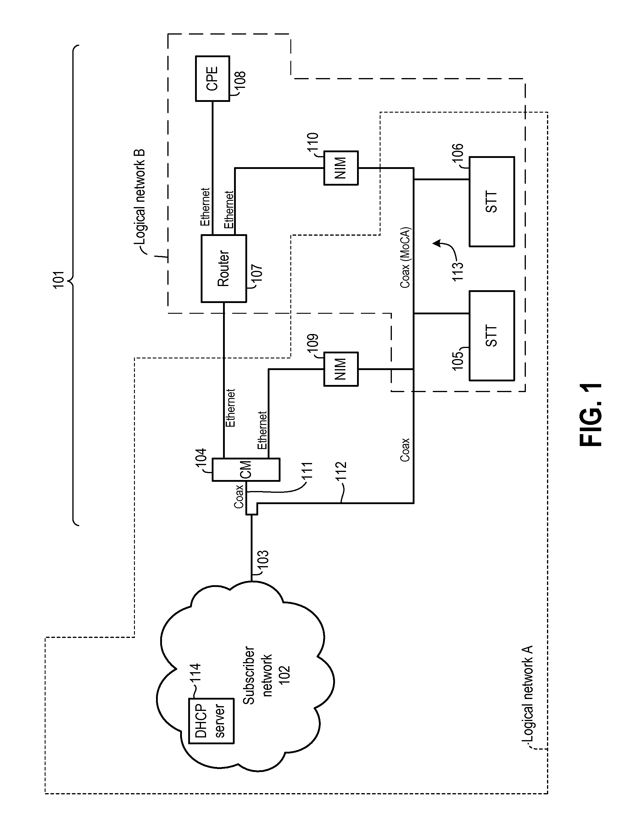
As used herein, and as the context requires, a “network” can be a logical or a physical network (or both). A physical network includes physically separate devices that communicate with each other across one or more types of communication media. A communication medium can be wired (e.g., coaxial cable, optical fiber, electrical conductor) or non wired (e.g., wireless radio communications through free space). A logical network includes devices that communicate across one or more types of communication media, but where all of those devices have an address recognized by one or more other devices in the same logical network. Two different logical networks can use the same communication medium (or media) and addressing protocol (e.g., internet protocol (IP) addresses). However, devices in a first of those logical networks may have addresses that are valid in the first logical network but not in a second of the logical networks. Similarly, devices in the second logical network may have add...


PUM


Abstract

A communication terminal communicates protocol data units across a first virtual interface and a shared interface. The first virtual interface corresponds to an upper layer protocol and a first logical network. The shared interface corresponds to a lower layer protocol. The terminal also communicates protocol data units across a second virtual interface and the shared interface, with the second virtual interface corresponding to the upper layer protocol and a second logical network. The first logical network can be a wide area network that includes devices within a premises and devices outside a premises, and the second logical network may be a local area network that only includes devices within the premises.

Description

BACKGROUNDSet top terminal (STT) devices are typically deployed in numerous premises throughout subscriber networks that serve numerous households and / or businesses over a wide region. STTs in a subscriber network receive programming from the network in a downstream direction, demodulate and otherwise process that data, and output content for display on a television or other customer device. STTs also communicate data upstream to the subscriber network head end. Subscriber networks used to deliver programming content are also used to provide high speed data and other types of services to subscribers, with those other services also requiring upstream and downstream communications with devices in a subscriber premises.Upgrade of subscriber network head ends to comply with the OCAP (OpenCable Application Platform) and DSG (DOCSIS Set-Top Gateway) specifications promulgated by Cable Television Laboratories, Inc. can result in some head ends that are no longer able to receive upstream si...

Claims


Application Information

Patent Timeline
Patent Type & Authority Applications(United States)
IPC IPC(8): H04J3/22
CPCH04L29/12226H04L29/12952H04L69/32H04L61/6077H04L69/14H04L61/2015H04L61/5014H04L2101/677H04L69/324
Inventor GILSON, ROSS
Owner TIVO CORP
Why Eureka
Try Eureka