Method and apparatus for effecting a minimally invasive distal anastomosis for an aortic valve bypass

a distal anastomosis and aortic valve technology, applied in the field of surgical methods and equipment, can solve the problems of not being able being one of the more difficult and time-consuming elements of aortic valve bypass, and being unable to perform aortic valve bypass

Inactive Publication Date: 2011-05-19
CORREX
View PDF6 Cites 19 Cited by
  • Summary
  • Abstract
  • Description
  • Claims
  • Application Information

AI Technical Summary

Benefits of technology

[0016]the hollow body of the second component being sized for coaxial disposition over the hollow body of the first component so that the outer collar of the second component can be adjustably positioned relative to the in

Problems solved by technology

In an aortic valve bypass procedure, the connection of the bypass conduit to the descending aorta is commonly referred to as the “distal anastomosis”, and is currently one of the more difficult and time-consuming elements of an aortic valve bypass procedure.
Aortic valve bypass is not currently a common procedure, at least in part due to the relatively difficult and time-consuming nature of the distal anastomosis.
Furthermore, aortic valve bypass cannot currently be considered to be a mi

Method used


Image

  • Method and apparatus for effecting a minimally invasive distal anastomosis for an aortic valve bypass
  • Method and apparatus for effecting a minimally invasive distal anastomosis for an aortic valve bypass
  • Method and apparatus for effecting a minimally invasive distal anastomosis for an aortic valve bypass

Examples


Embodiment Construction

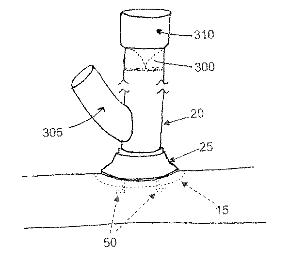
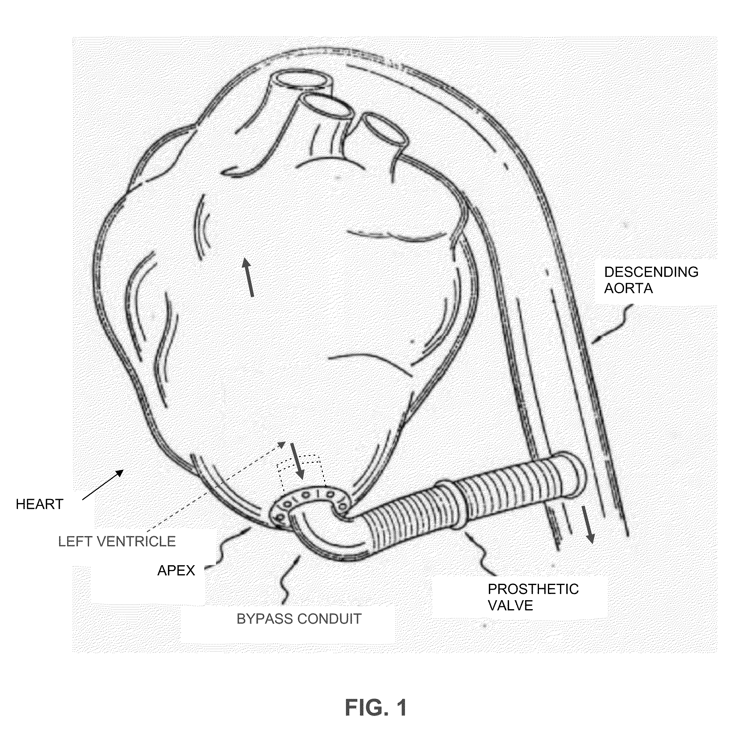
[0049]The present invention comprises a novel method and apparatus for effecting the distal anastomosis in an aortic valve bypass procedure. More particularly, the present invention comprises the provision and use of a novel locking collar connector to effect the distal anastomosis in an aortic valve bypass procedure. This novel locking collar connector allows the distal anastomosis to be effected quickly and safely, while requiring significantly less access to the anastomosis site and without requiring suturing to the descending aorta. Significantly, hemostasis is effectively maintained at substantially all times, so that the distal anastomosis can be carried out while the heart is beating.

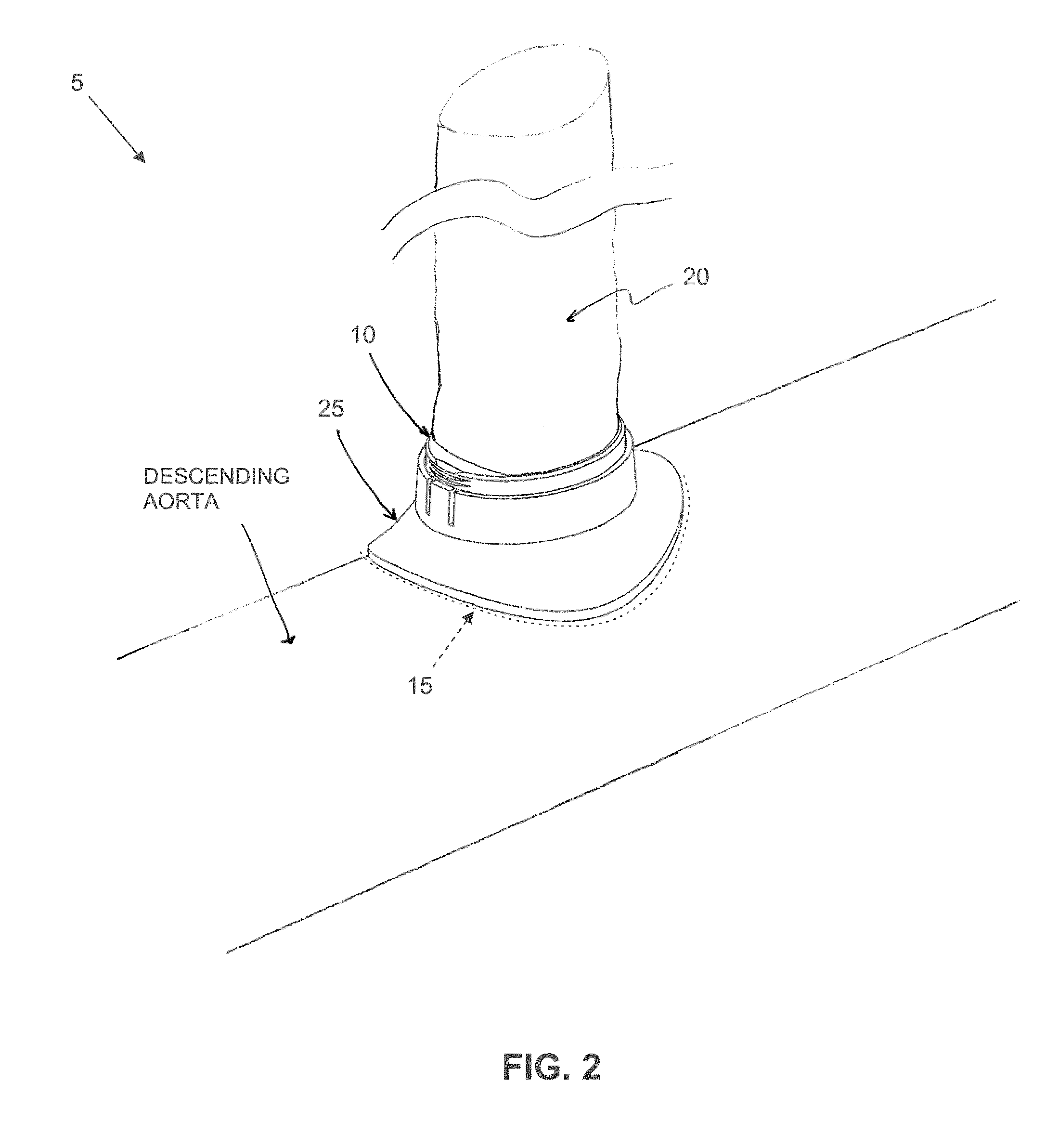
Locking Collar Connector

[0050]Looking now at FIGS. 2-7, there is shown a novel locking collar connector 5 which comprises one preferred form of the present invention. Locking collar connector 5 generally comprises a ratchet bracket 10 (FIGS. 2, 3, 5 and 6), an inner collar 15 (FIGS. 2, 4, 5 and 6...


PUM


Abstract

A connector for joining a first hollow structure to the side wall of a second hollow structure, the connector comprising:
    • a first component comprising:
      • an inner collar for disposition within the interior of the second hollow structure, the inner collar having a toroidal configuration characterized by an outer perimeter and an inner perimeter, with the inner collar being flexible;
      • a hollow body connected to the inner collar and upstanding therefrom, the hollow body of the inner collar being aligned with the inner perimeter of the inner collar; and
      • a graft element mounted to the inner collar and forming a conduit extending through the hollow body and the inner perimeter of the inner collar, the graft being formed out of a fluid-retaining material; and
    • a second component for disposition outside the second hollow structure, the second component comprising an outer collar and a hollow body connected to the outer collar, the outer collar having a toroidal configuration characterized by an outer perimeter and an inner perimeter, with the hollow body of the outer collar being aligned with the inner perimeter of the outer collar;
    • the hollow body of the second component being sized for coaxial disposition over the hollow body of the first component so that the outer collar of the second component can be adjustably positioned relative to the inner collar of the first component and so that the conduit of the graft element provides fluid communication between (i) the region beyond the inner collar, and (ii) the region beyond the hollow body of the first component.

Description

REFERENCE TO PENDING PRIOR PATENT APPLICATION[0001]This patent application claims benefit of pending prior U.S. Provisional Patent Application Ser. No. 61 / 234,075, filed Aug. 14, 2009 by Richard M. Beane et al. for MINIMALLY INVASIVE DISTAL ANASTOMOSIS FOR AORTIC VALVE BYPASS (Attorney's Docket No. CORREX-47 PROV), which patent application is hereby incorporated herein by reference.FIELD OF THE INVENTION [0002]This invention relates to surgical methods and apparatus in general, and more particularly to surgical methods and apparatus for effecting an aortic valve bypass.BACKGROUND OF THE INVENTION[0003]Aortic valve bypass is a proven procedure for relieving critical aortic valve stenosis. This procedure comprises the deployment of a bypass conduit, having a prosthetic valve disposed therein, between the left ventricle and the descending aorta. This approach allows blood to be pumped from the left ventricle into the descending aorta without requiring removal of the dysfunctional nativ...

Claims


Application Information

Patent Timeline
IPC IPC(8): A61B17/11
CPCA61B17/11A61B2017/1135A61B2017/1107A61B2017/00243A61B17/1114A61B2017/1121A61B2017/1132A61B2017/1139
Inventor BEANE, RICHARD M.BOUDREAU, RONALDCRUNKLETON, JAMES ALANLIEPERT, ANTHONY G.SMITH, JR., JOSEPH L.
Owner CORREX
Why Eureka
Try Eureka