Apparatus for measuring shape of test surface, and recording medium storing program for calculating shape of test surface
a technology for test surface and recording medium, which is applied in the direction of optical apparatus testing, reflective surface testing, instruments, etc., can solve the problems of optical system, two types of measurement errors generated by stitching methods, and accumulation of measurement errors
- Summary
- Abstract
- Description
- Claims
- Application Information
AI Technical Summary
Benefits of technology
Problems solved by technology
Method used
Image
Examples
example 1
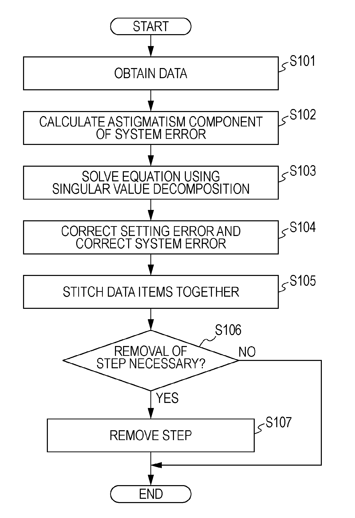
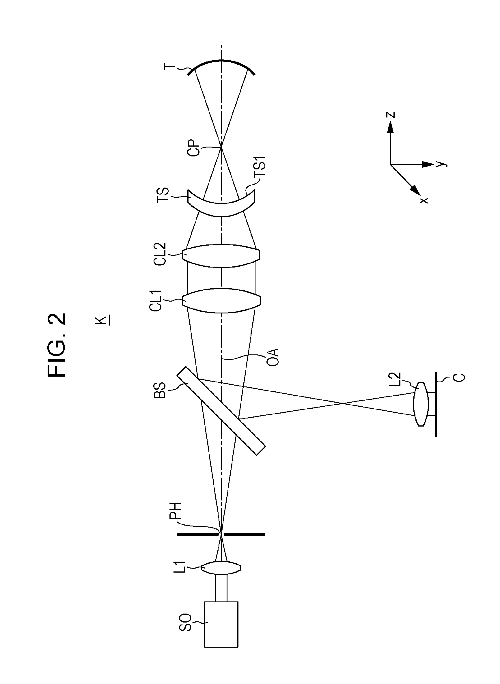
[0079]In the present example, stitching was performed on a test object that was a flat mirror. FIG. 6A illustrates the shape of a test surface of a flat mirror. The gradation shows concavities and convexities of the test surface. The flat mirror was a large mirror having a test surface with a long side larger than 1 m. The error between the actual shape of the test surface illustrated in FIG. 6A and an ideal plane was 206.5 nmRMS. FIG. 6B illustrates a state in which the test surface was divided into five partial regions S′1 to S′S and measured using a reference spherical wave forming lens TS having a diameter of 800 mm. White lines indicates the measurement regions. In the present example, N=5.
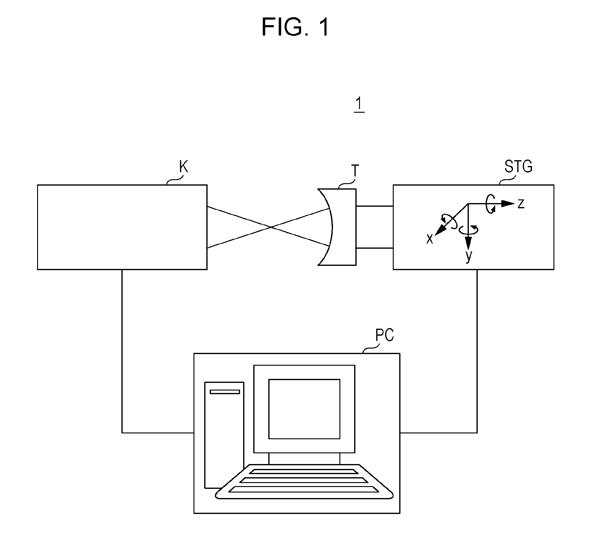
[0080]When the shape of the test surface was measured for the five partial regions S′1 to S′5, the measured shape was the sum of the actual shape of the test surface and errors, such as the positioning error of the stage STG (setting error) and the error of the interferometer (system error).
[...
example 2
[0087]In the present example, stitching was performed on an optical element having a spherical shape, such as a lens.
[0088]Measuring and stitching partial shapes of a sphere by using an interferometer is more complicated than measuring and stitching a planar shape. FIG. 10A illustrates the shape of a test surface and a state in which the test surface was divided into thirteen partial regions S″1 to S″13 and measured.
[0089]FIG. 10B illustrates the data of the partial shape of the partial region S″13 that was obtained when the stage STG was a six-axis stage and there was no positioning error. However, because the six-axis stage is expensive, a five-axis stage, which is comparatively low-cost, was used in the present example. A five-axis stage refers to a stage that has an xyz stage, a rotation mechanism around the x axis, and a rotation mechanism around the y axis. When measuring the partial region S″13 by using the five-axis stage, the test object was rotated around the x axis, and s...
example 3
[0095]In Examples described above, the measurement error is represented by the Zernike polynomial. In the present example, the stitching was performed by using a different polynomial. The measurement apparatus, the test object, and the measurement data were the same as those of Example 1.
[0096]As a polynomial for representing the measurement error, a function obtained by normalizing an xy polynomial by using the Gram-Schmidt process and being orthogonal in an effective circular region of the reference sphere forming lens TS was used. FIGS. 13A to 13I illustrate the first to the ninth terms of the orthogonal functions. In the xy polynomial, the first term is 1, the second term is x, the third term is y, the fourth term is x2, the fifth term is xy, the sixth term is y2, the seventh term is x3, the eighth term is x2y, the ninth term is xy2, the tenth term is y3, and the following terms are defined in the same manner.
[0097]FIG. 14 illustrates the result of stitching performed by using t...
PUM
 Abstract
Description
Claims
Application Information
 - R&D
- Intellectual Property
- Life Sciences
- Materials
- Tech Scout
- Unparalleled Data Quality
- Higher Quality Content
- 60% Fewer Hallucinations
Browse by: Latest US Patents, China's latest patents, Technical Efficacy Thesaurus, Application Domain, Technology Topic, Popular Technical Reports.
© 2025 PatSnap. All rights reserved.Legal|Privacy policy|Modern Slavery Act Transparency Statement|Sitemap|About US| Contact US: help@patsnap.com


