Method and apparatus for transmitting and receiving data in a communication system
a communication system and data technology, applied in the field of communication systems, can solve the problems of low-density parity check code, never commonly implemented, and large memory capacity required to store position information of a weight of 1
- Summary
- Abstract
- Description
- Claims
- Application Information
AI Technical Summary
Problems solved by technology
Method used
Image
Examples
embodiment 1
[0086]
Ntotal=Nadd—parity0+ . . . +Nadd—paritys-1<Nldpc−Kldpc
[0087]If a length of a parity part is greater than a sum of the numbers of elements in groups of additional parity bits, groups of additional parity bits are created based on parity bits of a codeword according to order of a puncturing pattern.
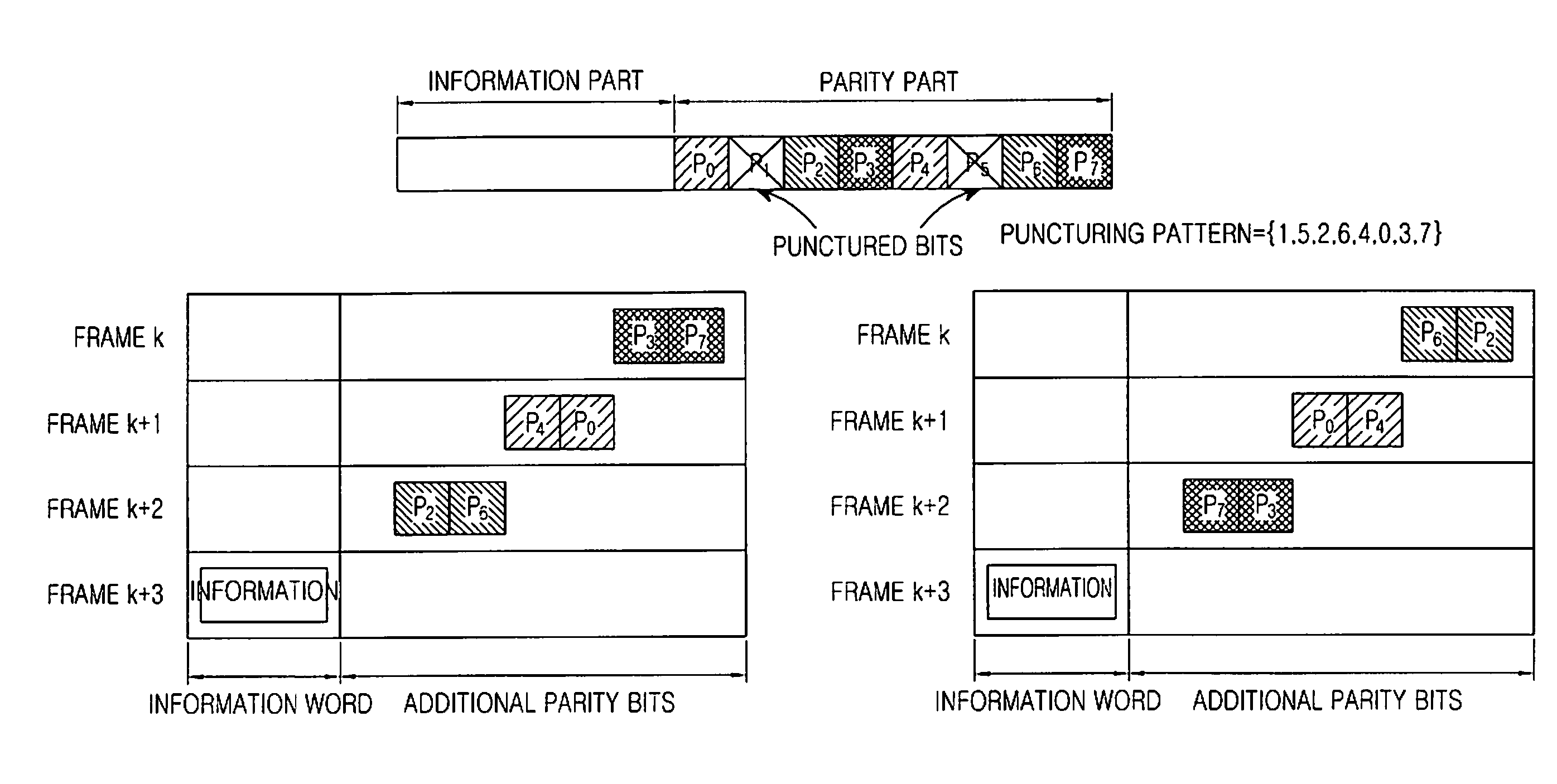
[0088]FIG. 5 illustrates a frame structure based on Rule 3 according to an embodiment of the present invention.
[0089]Referring to FIG. 5, a codeword includes an information part and a parity part. As an example, in FIG. 7, a length of the information part, after undergoing shortening, is 7 bits, I={i0, i1, . . . , i6}, the parity part is 8 bits in length, P={p0, p1, p2, . . . , p7}, and a puncturing pattern set representing puncturing order is A={1, 5, 2, 6, 4, 0, 3, 7}.
[0090]For Npunc=2, s=3, and Nadd—parity0=Nadd—parity1=Nadd—parity2=2 (where Npunc is the number of punctured bits, s is the number of frames on which additional parity bits are transmitted, and Nadd—parity0, Nadd—p...
embodiment 2
[0095]
Ntotal=Nadd—parity0+ . . . +Nadd—paritys-1<Nldpc−Kldpc
[0096]If a length of a parity part is less than or equal to a sum of the numbers of elements in groups of additional parity bits, groups of additional parity bits are created based on parity bits and information bits of a codeword.
[0097]Again, a codeword includes an information part and a parity part. Using the same example as above, a length of the information part, after undergoing shortening, is 7 bits, I={i0, i1, . . . , i6}, the parity part is 8 bits in length and is P={p0, p1, p2, . . . , p7}, and a puncturing pattern set representing puncturing order is A={1, 5, 2, 6, 4, 0, 3, 7}.
[0098]For Npunc=2, s=3, and Nadd—parity0=Nadd—parity1=Nadd—parity232 3 (where Npunc is the number of punctured bits, s is the number of frames on which additional parity bits are transmitted, and Nadd—parity0, Nadd—parity1, and Nadd—parity2 are the numbers of additional parity bits transmitted on their associated frames), groups of addit...
embodiment 3
[0126]FIG. 7 illustrates a frame structure based on Rule 4 according to an embodiment of the present invention.
[0127]Referring to FIG. 7, a codeword includes an information part and a parity part. Using the same example as above, a length of the information part, after undergoing shortening, is 7 bits, I={i0, i1, . . . , i6}, the parity part is 8 bits in length, P={p0, p1, p2, . . . , p7}, and a puncturing pattern set representing puncturing order is A={1, 5, 2, 6, 4, 0, 3, 7}.
[0128]For Npunc=2, s=3, and Nadd—parity0=Nadd—parity1=Nadd—parity2=2 (where Npunc is the number of punctured bits, s is the number of frames on which additional parity bits are transmitted, and Nadd—parity0, Nadd—parity1, and Nadd—parity2 are the numbers of additional parity bits transmitted on their associated frames), groups of additional parity bits are created as described below. It is assumed that a parity check matrix corresponding to the parity part is a dual diagonal matrix in structure.
[0129]Because t...
PUM
 Abstract
Description
Claims
Application Information
 - R&D
- Intellectual Property
- Life Sciences
- Materials
- Tech Scout
- Unparalleled Data Quality
- Higher Quality Content
- 60% Fewer Hallucinations
Browse by: Latest US Patents, China's latest patents, Technical Efficacy Thesaurus, Application Domain, Technology Topic, Popular Technical Reports.
© 2025 PatSnap. All rights reserved.Legal|Privacy policy|Modern Slavery Act Transparency Statement|Sitemap|About US| Contact US: help@patsnap.com


