

Falling water electrical generators and electrical generating methods
a technology of electrical generators and water sources, applied in sea energy generation, mechanical equipment, machines/engines, etc., can solve the problems of difficulty in extracting electrical energy from falling water sources, electrical generators known in the art have not been used in conjunction with water sources, and low efficiency of such technologies
- Summary
- Abstract
- Description
- Claims
- Application Information
AI Technical Summary
Benefits of technology
Problems solved by technology
Method used
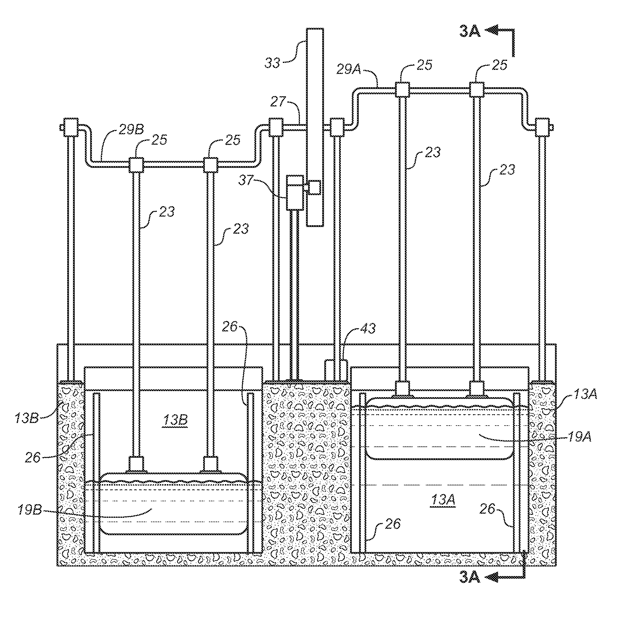
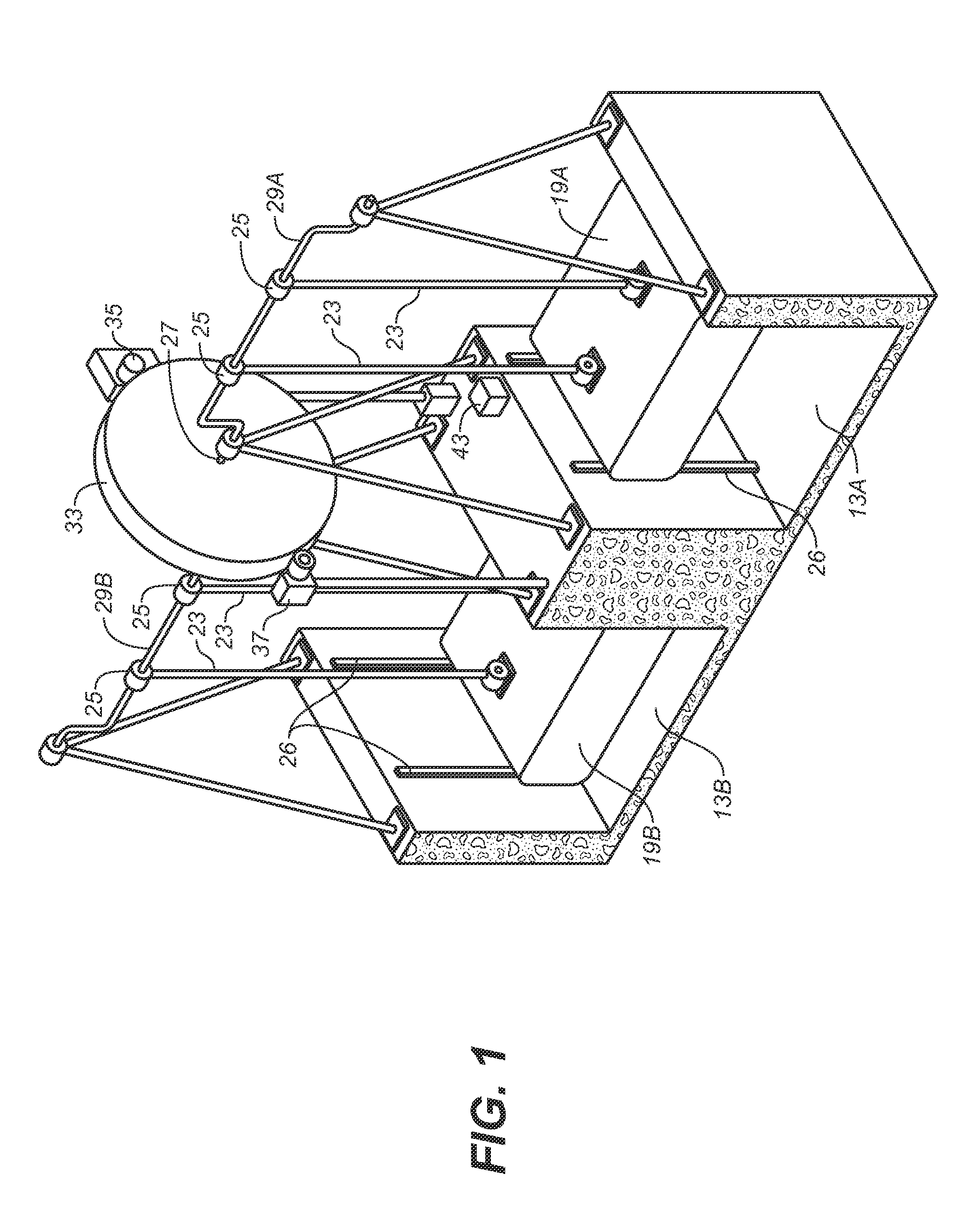
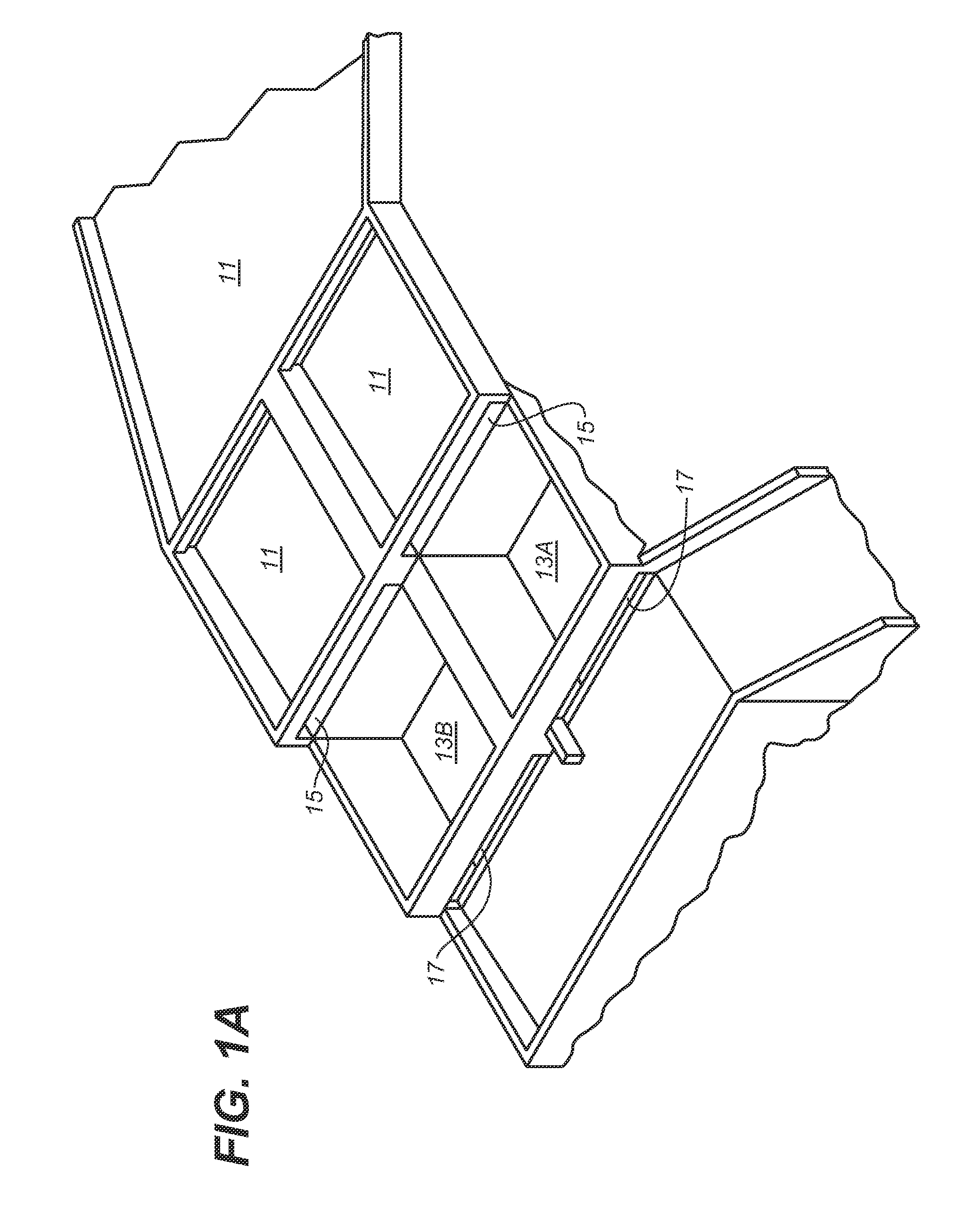
Image

Examples
Embodiment Construction
[0026]Before describing the present invention in detail, it is to be understood that the invention is not limited to specific electrical generators, as such may vary. It is also to be understood that the terminology used herein is for describing particular embodiments only, and is not intended to be limiting.
[0027]In addition, as used in this specification and the appended claims, the singular article forms “a,”“an,” and “the” include both singular and plural referents unless the context of their usage clearly dictates otherwise. Thus, for example, reference to “a float” includes a plurality of floats as well as a single float, reference to “a reservoir” includes a single reservoir as well as a collection of reservoirs, and the like.
[0028]In this specification and in the claims that follow, reference will be made to a number of terms that shall be defined to have the following meanings, unless the context in which they are employed clearly indicates otherwise:
[0029]The term “connect...
PUM
 Abstract
Description
Claims
Application Information