Casing for heating/cooling units

a cooling unit and cooling chamber technology, applied in the field of cooling/heating units, can solve the problems of reducing the energy efficiency of the cooling/heating unit, reducing the energy efficiency of the building itself, etc., and achieve the effect of easy and efficient manufacturing and marketing

Inactive Publication Date: 2011-05-26
ICE AIR
View PDF14 Cites 75 Cited by
  • Summary
  • Abstract
  • Description
  • Claims
  • Application Information

AI Technical Summary

Benefits of technology

[0004]Accordingly, it is an object of the present invention to provide a new and improved

Problems solved by technology

This decreases the energy efficiency of the cooling/heating unit, by allowing unwanted

Method used


Image

  • Casing for heating/cooling units
  • Casing for heating/cooling units

Examples


Embodiment Construction

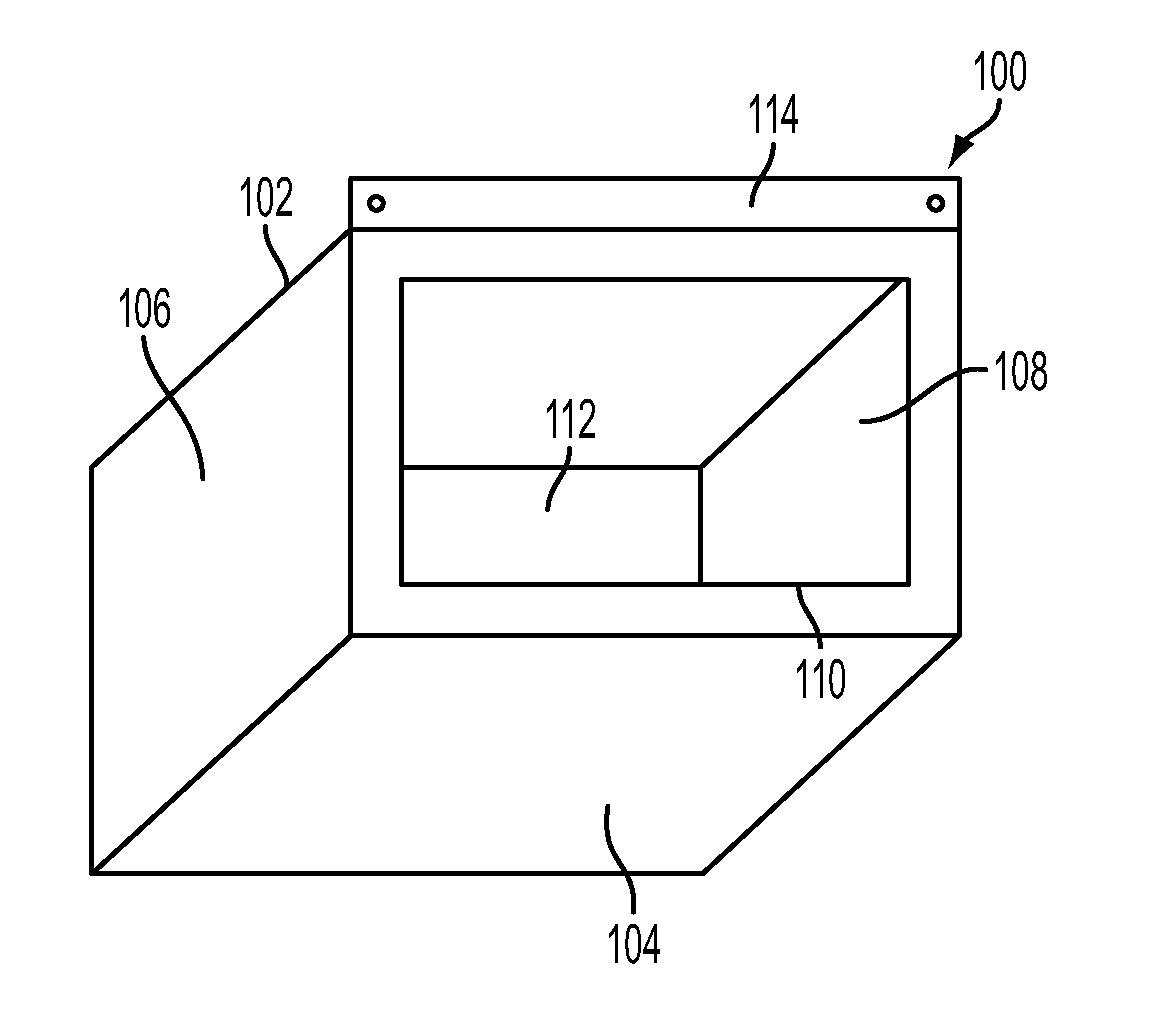
[0013]With reference now to the drawings, a new and improved casing for heating / cooling units embodying the principles and concepts of the present invention is described. More specifically, referring to FIG. 1, the heating / cooling unit casing 100 essentially comprises a structure formed with a top side 102, a bottom side 104, a first lateral side 106 orthogonally formed to the top side 102 and bottom side 104, and a second lateral side 108 parallel to said first lateral side 106. The fours sides together form a box with open front side 110 and back side 112. In use, the back side 112 is opened to the outside of the building, while the front side 110 is opened to the inside of the building.

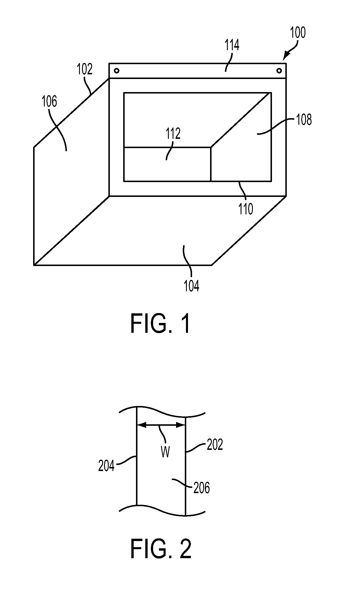
[0014]The top 102, bottom 104, and lateral 106, 108 sides of the casing 100 are each preferably double walled. Referring to FIG. 2, which shows the double wall of each of the sides of the casing 100, each of the sides contains an inner wall 202 and an outer wall 204. The space 206 between the inner...


PUM

PropertyMeasurementUnit
aaaaaaaaaa

Abstract

The present invention relates to cooling/heating units and their installation to wall or window openings, and more particularly pertains to a new and improved casing to secure the air conditioner while protecting against heat leakages through the casing itself. The wall casing is a cabinet structure containing a top side, a bottom side opposing the top side, and two opposing lateral sides being approximately orthogonal to the top and bottom sides. The top, bottom, and lateral sides forming substantially a box with the front and back opened. Each of the sides is double-walled and filled with an insulating material.

Description

FIELD OF THE INVENTION[0001]The present invention relates to cooling / heating units and their installation to wall or window openings, and more particularly pertains to a new and improved casing to secure and seal the heating / cooling unit while protecting against heat exterior-to-interior (or vice versa) heat transfer and / or heat leakage through the sleeve itself.BACKGROUND OF THE INVENTION[0002]The use of through the wall or window mounted air conditioning units is well known. These units are manufactured of varying cooling capacities between, for example, 6,000 BTU / hour through 36,000 BTU / hour ratings. Through-the-wall units , a subsection of which, when incorporating heating capabilities within the unit, are referred to as Packaged Terminal Air Conditioners (PTACs) and / or Packaged Terminal Heat Pumps (PTHPs), employ air intakes and exhaust on the rear (exterior) surface of the. Unit. Window mounted units employ similar rear air intake and exhaust, with the addition of side vents t...

Claims


Application Information

Patent Timeline
IPC IPC(8): F25D23/00B23P19/04
CPCF24F1/027Y10T29/53F24F13/20F24F13/0263
Inventor NADEL, FREDRICSIEGEL, MOSHE MICHAELFU, QIANLI
Owner ICE AIR
Why Eureka
Try Eureka