Retracta Belt Brake System

a belt and brake technology, applied in the direction of traffic signals, roads, transportation and packaging, etc., can solve the problems of belt mechanism inoperable, spring mechanism can, and often do, break, etc., and achieve the effect of reducing the rotation rate of the belt cassette assembly

Inactive Publication Date: 2011-05-26
VISIONTRON CORP
View PDF16 Cites 21 Cited by
  • Summary
  • Abstract
  • Description
  • Claims
  • Application Information

AI Technical Summary

Benefits of technology

[0013]It is also an object of the present invention to provide a pedestrian traffic control stanchion including a post having an upper end and a lower end; a belt cassette assembly mounted on an upper end of the post; a spring case assembly positioned adjacent to and operatively connected to the belt cassette assembly to provide tension on a belt as the belt is extracted from the belt cassette assembly; a brake case assembly positioned adjacent to the belt cassette assembly and operatively connected to the belt cassette assembly to dampen the rate of rotation of the belt cassette assembly as the belt is retracted into the belt cassette assembly under the tension force exerted by the ...

Problems solved by technology

Although belt stanchion posts with internal belts are convenient, spring rewind mechanisms have limitations.
Spring mechanisms can, and frequently do, break.
Breakage renders the belt mechanism inoperable.
Also, releasing a completely extended belt may cause it to rewind with excessive speed, thereby...

Method used


Image

  • Retracta Belt Brake System
  • Retracta Belt Brake System
  • Retracta Belt Brake System

Examples


Embodiment Construction

[0030]The following description is presented to enable one of ordinary skill in the art to make and use the invention and is provided in the context of a patent application and its requirements. Various modifications to the preferred embodiments will be readily apparent to those skilled in the art and the generic principles herein may be applied to other embodiments. Thus, the present invention is not intended to be limited to the embodiment shown but is to be accorded the widest scope consistent with the principles and features described herein.

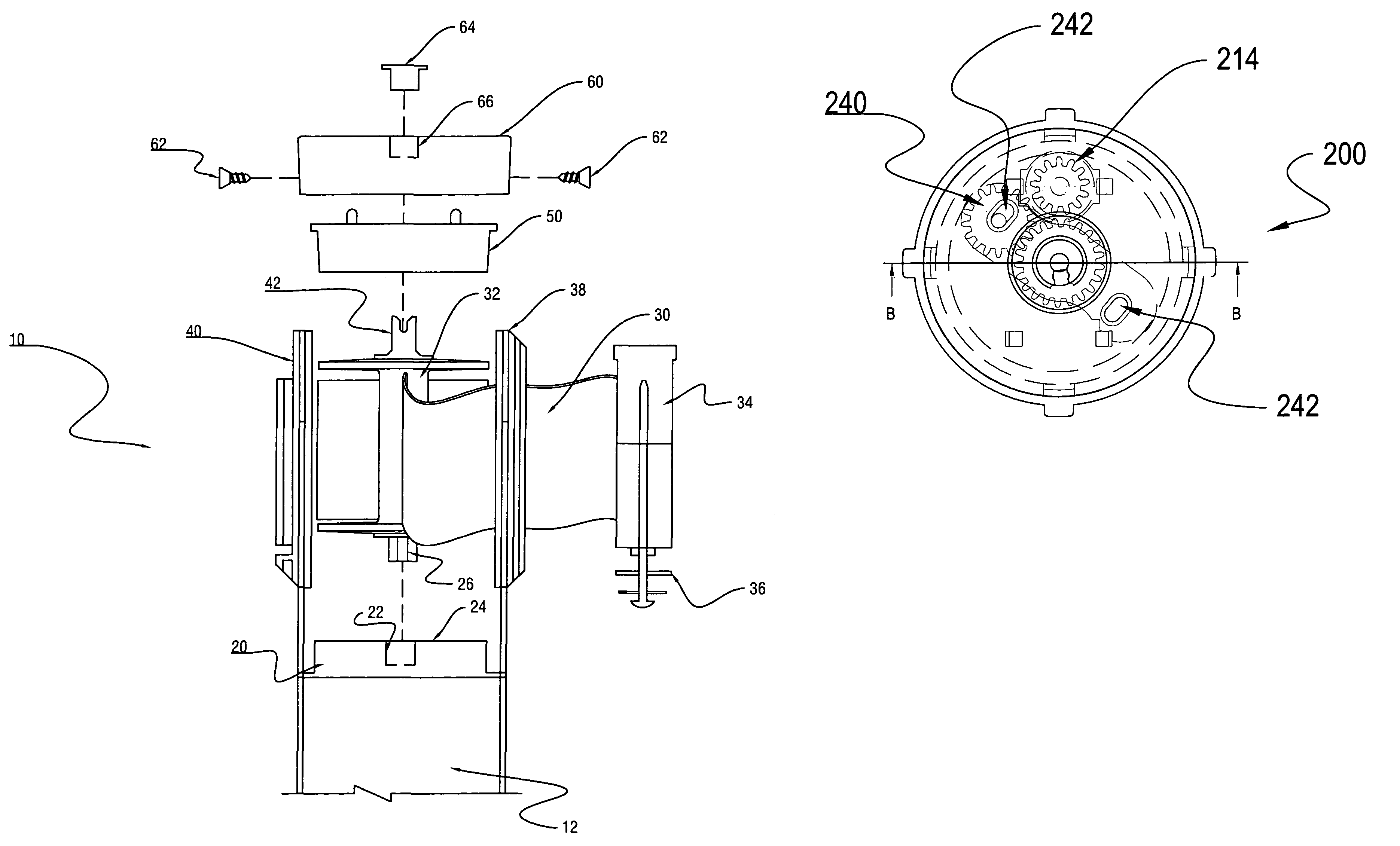
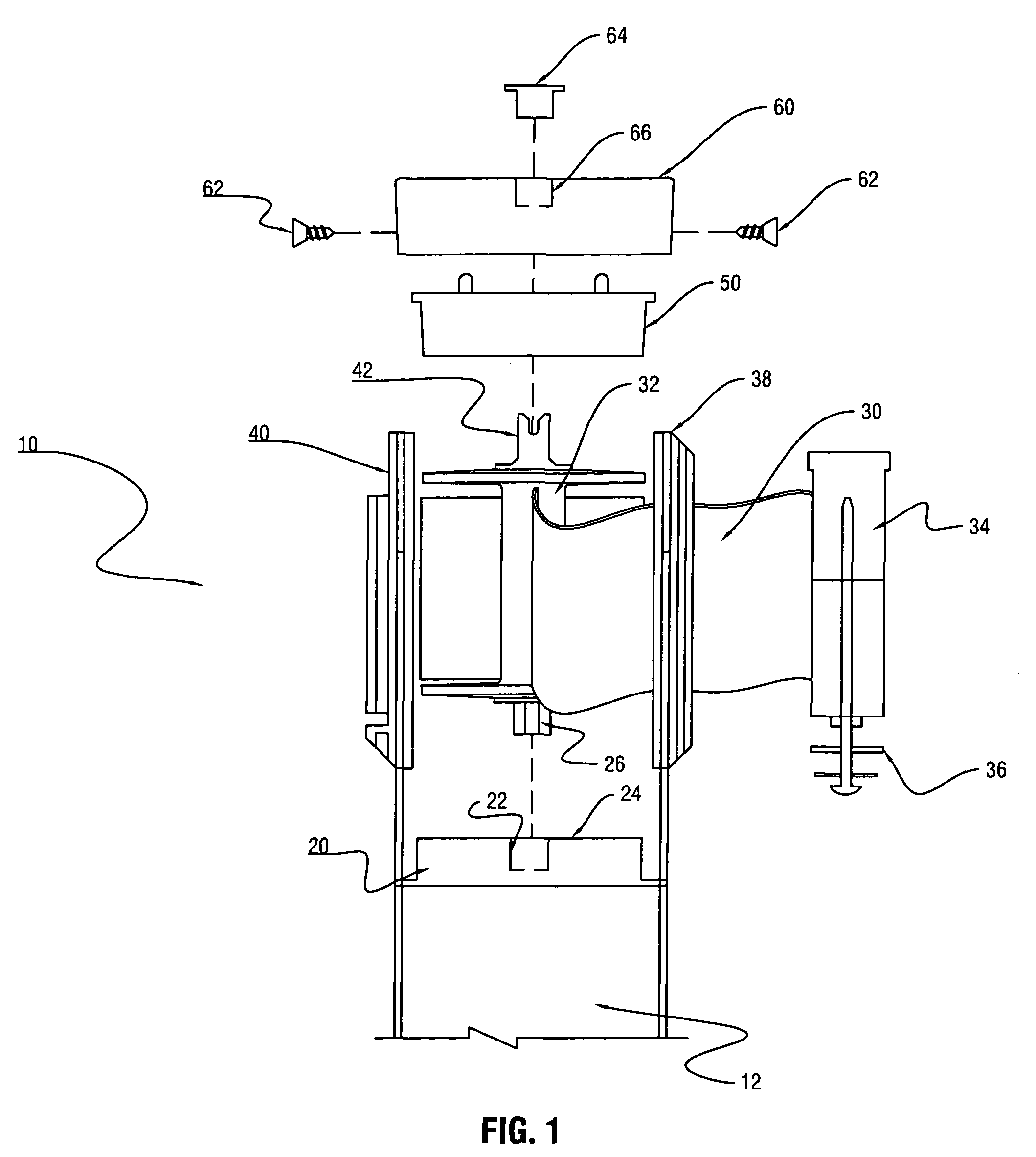
[0031]Referring now to the drawings in detail, and initially to FIG. 1, components of a belt cassette assembly 10 mounted on an upper end of a post or stanchion 12, in accordance with an embodiment of the present invention, is illustrated. Brake case assembly 20 is positioned at a lower end of belt cassette assembly 10. Although the brake case is illustrated at the lower end of the belt cassette assembly, it is contemplated that the brake ca...


PUM


Abstract

A pedestrian traffic control stanchion including a post having an upper end and a lower end; a belt cassette assembly mounted on an upper end of the post; a spring case assembly positioned adjacent to and operatively connected to the belt cassette assembly to provide tension on a belt as the belt is extracted from the belt cassette assembly; a brake case assembly positioned adjacent to the belt cassette assembly and operatively connected to the belt cassette assembly to dampen the rate of rotation of the belt cassette assembly as the belt is retracted into the belt cassette assembly under the tension force exerted by the spring case assembly; the brake case assembly including a housing, a drive gear positioned within the housing, said drive gear being configured to be connected to the belt cassette assembly, a floating gear positioned within the housing in a position to engage the drive gear, the floating gear having an axial shaft extending therefrom, wherein the axial shaft of the floating gear is positioned within a slot formed in the housing, the slot having a first end and a second end; and a gear driven damper assembly positioned within the housing and configured to engage the floating gear when the axial shaft of the floating gear is positioned in one of the first end or the second end.

Description

BACKGROUND OF THE INVENTION[0001]1. Field of the Invention[0002]The present invention relates to pedestrian traffic control stanchion posts, and, more specifically, to a brake system used to control the retraction of a belt within the pedestrian traffic control stanchion post.[0003]2. Description of the Background Art[0004]This invention relates to pedestrian traffic control barriers of the type including a vertical post or stanchion, and a cassette mounted on the upper end of the post or stanchion, the cassette incorporating a flexible tape or belt wound on a spool, the tape or belt being extendable in a horizontal direction from the post. The tape or belt is extended by pulling on its free end, causing the tape to unwind from a spool within the cassette against the force of a retractor spring tending to rotate the spool so as to rewind the tape. The free end of the tape is attached to the upper end of another similar post, or in some cases to a fixed bracket on a wall, so as to es...

Claims


Application Information

Patent Timeline
IPC IPC(8): F16D59/00B65H23/18E01F9/019E01F9/646
CPCE01F13/028
Inventor HANSEN, CHARLESTORSIELLO, BRYAN
Owner VISIONTRON CORP
Why Eureka
Try Eureka