Spraying device

a spray device and spraying technology, applied in the direction of spraying apparatus, spraying apparatus, movable spraying apparatus, etc., can solve the problems of difficult miniaturization, large volume, and complex structure of the motor driven system, and achieve the effect of promoting the leakage of liquid spray and improving the working effect of the system

Inactive Publication Date: 2011-05-26
HAN TIE FU
View PDF4 Cites 38 Cited by
  • Summary
  • Abstract
  • Description
  • Claims
  • Application Information

AI Technical Summary

Benefits of technology

Another advantage of the invention is to provide a rotary spray which may be applied in other spray fields such as dust removal, drying or combustion to improve the working effect thereof.
is to provide a rotary spray which may be applied in other spray fields such as dust removal, drying or combustion to improve the working effect thereof.
Another advantage of the invention is to provide a jet push rotary spray device which may be automatically rotated under a reaction force of spray flow from the eccentric spray openings, and may solve the difficult problem of large-area uniform spray and fine atomization under a low or medium pressure.
One technical solution of the present invention is to provide a jet push rotary spray device.
The jet push rotary spray device includes a hollow seat body and a spray head body being rotatable relative to the seat body. The seat body is provided with a seat body cavity, and the entrance of the seat body cavity is threadedly connected with an external fluid input pipe. A fluid passage is provided inside the spray head body, and spray openings are provided outside the spray head body. Each spray opening communicates with the fluid passage which is in turn communicating with the entrance of the seat body cavity. The spray openings of the spray head body at least include two eccentric spray openings being symmetrical relative to the axis of the spray device. The centerline of each eccentric spray opening doesn't intersect with the centerline of the spray device. The spray flow reaction force of each eccentric spray opening may impart a rotation torque on the spray head body in the same direction, and the rotation direction of the rotation torque is identical with the tighten direction of the connection thread on the spray device. There are rotation engagement surfaces between the spray head body and the seat body, and the rotation engagement surfaces may be lubricated by liquid leaking through a rotation engagement surface clearance. The clearance of at least one of the rotation engagement surfaces, which is likely to leak liquid towards outside, may be designed as an annular spray opening. A small amount of fluid may be sprayed through the annular spray opening.
The annular spray opening is a rotation engagement surface clearance annular slot with or without an enlarged opening. A plurality of radial narrow ditches may be provided on one surface of the clearance annular slot. Preferably, the radial narrow ditches are in tangential radial shape, and the entrance section of each narrow ditch is larger than the outlet section thereof. An annular groove may be additionally provided at the inner side of the entrance of the above two kinds of clearance annular slot, and communicate with the fluid passage via a fluid introducing hole.

Problems solved by technology

However, the motor driven system has a complex structure, a large volume, and needs a rotational power externally provided.
Since they have a relatively large volume and rotational inertia, they rotate slowly, sprinkle or spray big liquid drops, and is difficult in miniaturization, which cannot meet the strict requirements of strong force and fine atomization.
It is difficult for the fixed type spray head to uniformly and completely cover all fire in a whole space, and this affects the fire extinguishing effect.
However, it has a large structure, rotates slowly, and sprays large water stream and large water drops, and thus cannot appropriately form mist and are not suitable for extinguishing oil fire.
The conventional pressure atomization small circular hole fixed spray mode has the following disadvantages which are difficultly resolved, e.g. a contradiction between flow rate and fine atomization and a contradiction between fine atomization and spray momentum.
Therefore, the performance of conventional fixed fire fighting spray head is not ideal.

Method used


Image

  • Spraying device
  • Spraying device
  • Spraying device

Examples


embodiment 1

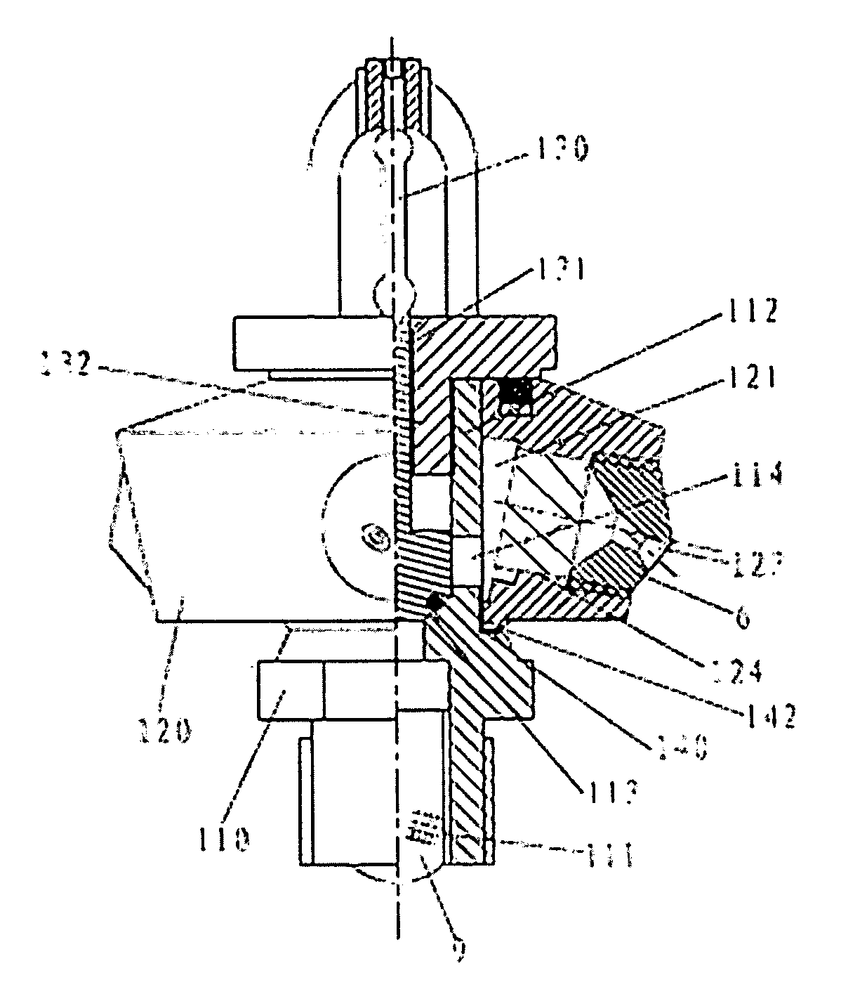
Referring to FIGS. 1, 1-1 and 1-2, the jet push rotary spray device according to the embodiment is a jet push rotary closed type spray device with a sleeved type spray head body, which mainly includes a seat body 110 and a spray head body 120 (as shown in FIG. 1).

The seat body 110 has a hollow structure, and has an entrance 111 provided at one end of the seat body 110. A filter 9 is provided in the entrance 111. An outer surface of the entrance 111 is threaded to connect with an input flow pipe (not shown in the drawings). The seat body 110 is further provided with a hollow shaft 112. Rotational flow openings 114 are disposed along the axial direction of the hollow shaft 112 and formed by inclined through holes on the wall of the hollow shaft 112.

The spray head body 120 is a rotor body, and may be embodied in various shapes. In this embodiment, the spray head body 120 is a truncated polyhedral cone with a central through hole. The spray head body 120 is rotatably installed on the ho...

embodiment 2

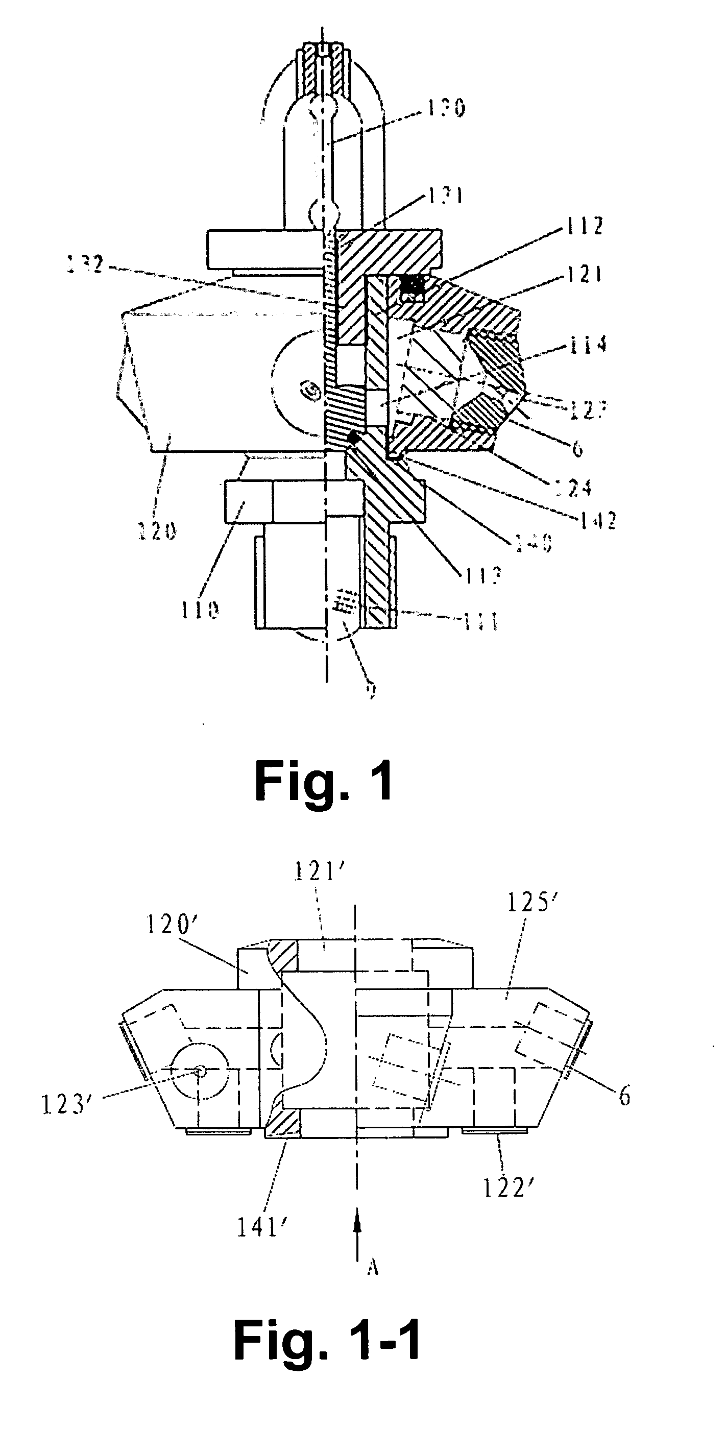
As shown in FIGS. 2, 2-1 and 2-2, the jet push rotary spray device according to the embodiment also includes the seat body 210 and the spray head body 220.

The seat body 210 has a hollow structure, and its outer wall is threaded to connect with an input flow pipe (not shown in figures). An upper annular surface 215 and a lower annular surface 216 are respectively provided above the inner hole 212 of the seat body 210 and at the outlet.

An entrance pipe 226 is provided above the spray head body 220, and an analogy assembled square body 225 is provided below the spray head body 220. The entrance pipe 226 is rotatably inserted in the inner hole 212 of the seat body 210. A circular step 227 and a collar 224 are provided on the outer circumference of the entrance end of the entrance pipe 226 of the spray head body 220. The top circular ring of the periphery of the spray head body 220 exposed outside the inner hole 212 of the seat body 210 forms a lower circular step 228 and an upper circul...

embodiment 3

As shown in FIGS. 3, 3-1, 3-2 and 3-3, the jet push rotary spray device according to the embodiment also includes the seat body 310 and the spray head body 320.

The seat body 310 is hollow in structure, wherein an entrance 311 is provided at one end of the seat body 310. A filter 9 is provided in the entrance 311. The outer surface of the entrance 311 is threaded to connect with an input flow pipe (not shown in Figures). An upper annular surface 315 and a lower annular surface 316 are respectively provided above the inner hole 312 of the seat body 310 and at the outlet.

The spray head body 320 is a space generatrix revolving solid. The cavity inside the spray head body 320 forms a fluid passage 321. The spray head body 320 includes an entrance pipe 326, a spray head body seat 3201 and a spray head body main part 3202 which are separate components. The entrance pipe 326 is rotatably inserted in the inner hole 312 of the seat body 310 to play a role of positioning in the radial directio...


PUM


Abstract

A rotary spray device includes a seat body having an entrance and a spray head bodyin which a fluid passage is provided. The rotary spray device further includes at least one impeller. The entrance communicates with the fluid passage by a fluid chamber. The impeller is located within the fluid chamber and is rotated with the spray head body. The spray head body is rotatably connected with the seat body. Preferably, the spray head body has eccentric spray nozzles, and the minimal distance is not zero between the center lines of the eccentric spray nozzles and the rotation center line of the spray head body, and the center lines do not parallel the rotation center line. The rotation center line of spray head body is an axis about which the spray head body rotates relative to the seat body. The spray device according to the present invention rotates the spray head body by the drive of the fluid energy, to perform a pressure pray, and may also spray leak liquid through the rotation clearance. It has a simple, compact structure, and may achieve a good effect.

Description

CROSS REFERENCE OF RELATED APPLICATION The present application claims the benefit of priority to Chinese patent application No. 200810071432.6 titled “SELF-DRIVING ROTARY DISPENSING DEVICE”, filed with the Chinese State Intellectual Property Office on Jul. 18, 2008, and the benefit of priority to Chinese patent application No. 200910111270.9 titled “JET PUSH ROTARY SPRAY HEAD”, filed with the Chinese State Intellectual Property Office on Mar. 9, 2009. The entire disclosure thereof is incorporated herein by reference.BACKGROUND OF THE PRESENT INVENTION 1. Field of InventionThe present invention relates to sprinkling technology, in particular to a rotary spray device which is mainly applied in fire fighting field, and more specifically to a spray device used in automatic fire extinguishing system and in other spray applications such as spray dust removal, spray drying, spray combustion and spray irrigation.2. Description of Related ArtsConventional rotary sprays such as a centrifugal ...

Claims


Application Information

Patent Timeline
Patent Type & Authority Applications(United States)
IPC IPC(8): B05B3/04
CPCA62C31/05A62C37/14B05B7/0425B05B3/06B05B3/0427
Inventor HAN, TIEFU
Owner HAN TIE FU
Why Eureka
Try Eureka