

Circuit for detecting management engine state
- Summary
- Abstract
- Description
- Claims
- Application Information
AI Technical Summary
Problems solved by technology
Method used
Image

Examples
Embodiment Construction
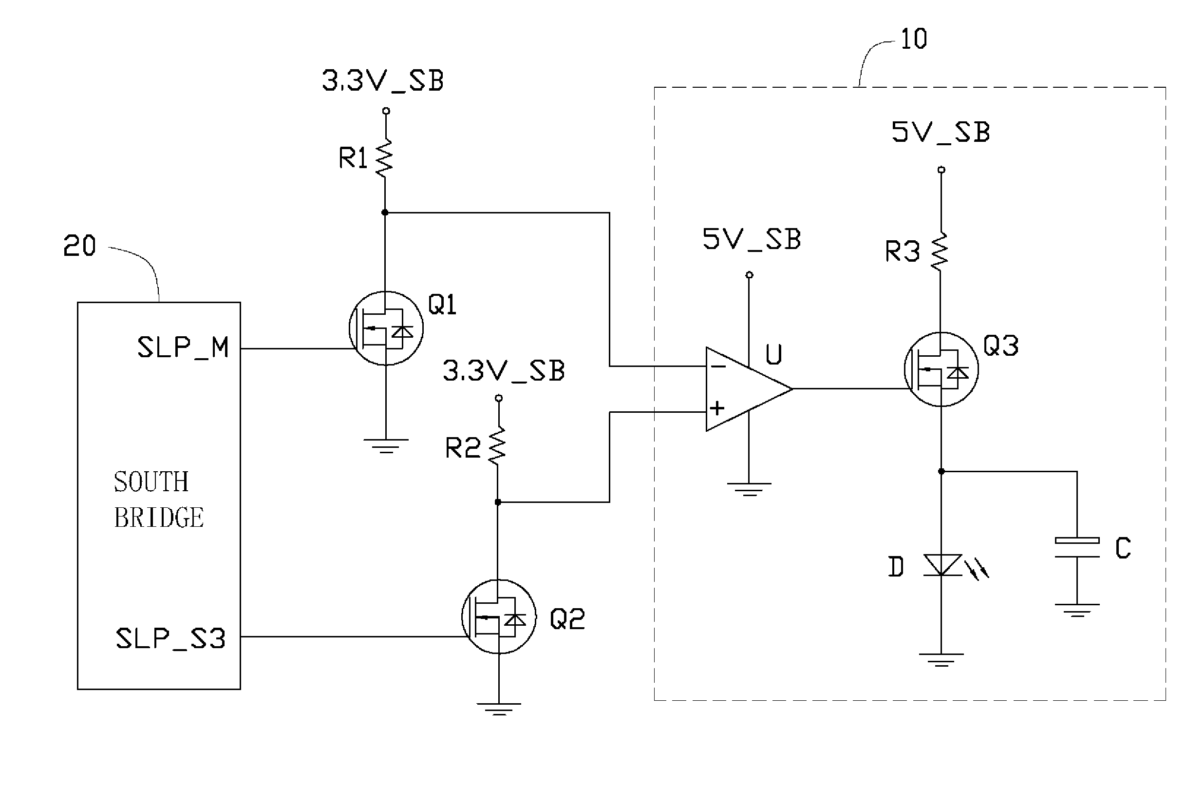
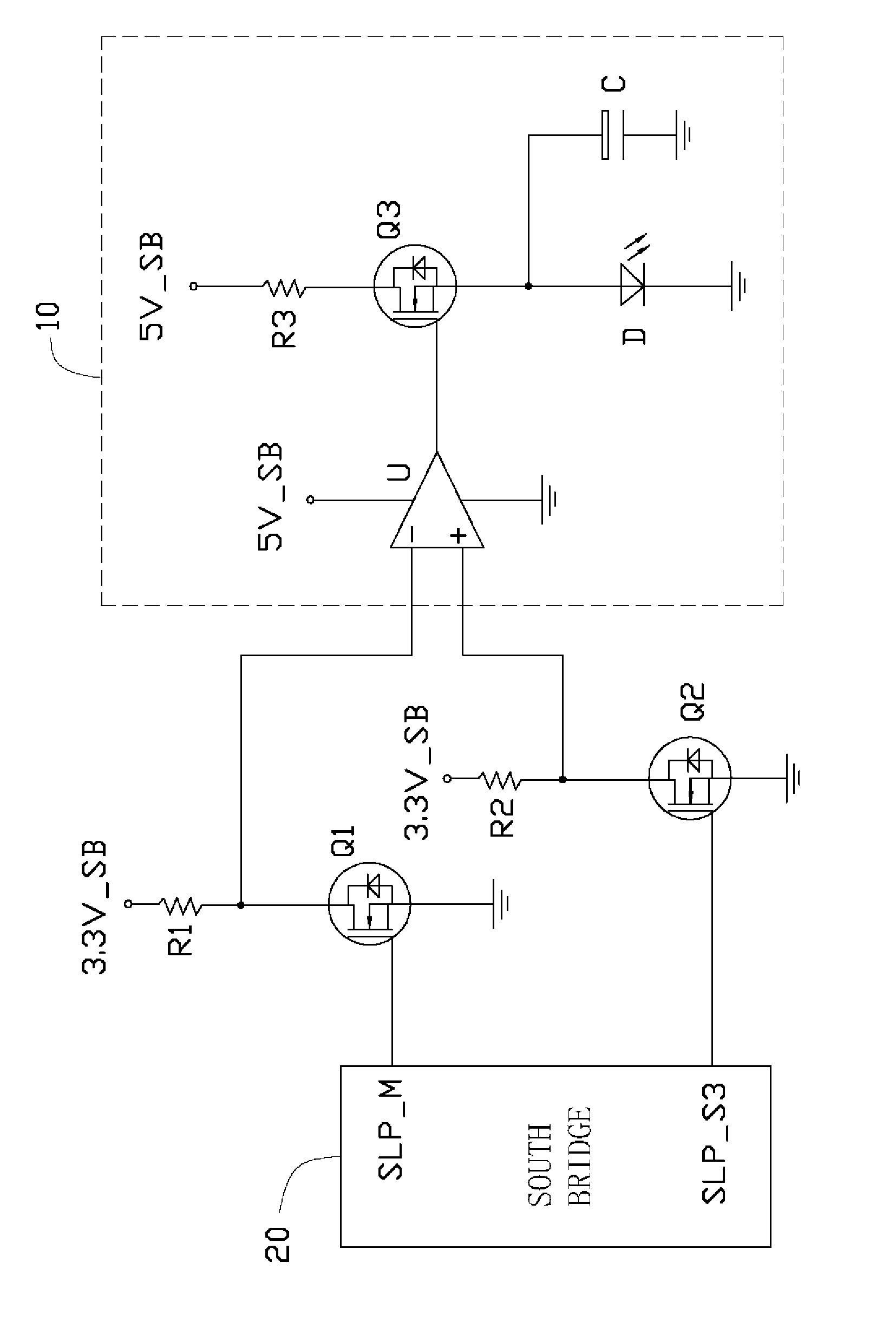
[0008]Referring to the drawing, an exemplary embodiment of a circuit for detecting management engine (ME) state of a computer includes two n-channel metal-oxide-semiconductor field-effect transistors (MOSFET) Q1 and Q2 and an indicating circuit 10. The indicating circuit 10 includes a comparator U, an n-channel MOSFET Q3, a light-emitting diode (LED) D, and a capacitor C.
[0009]A gate of the MOSFET Q1 is connected to a ME state pin SLP_M of a south bridge 20 of a motherboard of the computer, a drain of the MOSFET Q1 is connected to a first power supply 3.3V_SB via a first resistor R1, a source of the MOSFET Q1 is grounded. A gate of the MOSFET Q2 is connected to a system startup pin SLP_S3 of the south bridge 20 of a computer, a drain of the MOSFET Q2 is connected to the first power supply 3.3V_SB via a second resistor R2, a source of the MOSFET Q2 is grounded. An inverting terminal and a non-inverting terminal of the comparator U are respectively connected to the drains of the MOSFE...
PUM
 Abstract
Description
Claims
Application Information