Phased array antenna having integral calibration network and method for measuring calibration ratio thereof

a phased array antenna and integral calibration technology, applied in the direction of antennas, instruments, wave based measurement systems, etc., can solve the problems of high cost, inability to compensate for small differences in phase, and interference between signals transmitted through antenna elements

Active Publication Date: 2011-05-26
ELTA SYST LTD
View PDF8 Cites 67 Cited by
  • Summary
  • Abstract
  • Description
  • Claims
  • Application Information

AI Technical Summary

Benefits of technology

[0051]It would therefore clearly be desirable to make possible calibrating array ant...

Problems solved by technology

The signals transmitted through the antenna elements interfere with each other.
Since the replacement antenna elements will inevitably have slightly different properties to the original antenna elements, the original offsets will not compensate for slight differences in the phase and gain characteristics of the phase shifters and amplifiers used to feed steering signals to the replacement antenna elements.
Such calibration networks are available but they require sophisticated electronics and are expensive.
This, of course, greatly simplifies the determination of calibration ratio, but is not feasible when there is insufficient space between the external calibration source and the phased array antenna, such as when a phased array antenna is recalibrated in the field.
This also ensures that the respective amplitudes and phases of the external calibration signals injected into each antenna element are the same, but requires critical and consequently complex alignment and is both time-consu...

Method used


Image

  • Phased array antenna having integral calibration network and method for measuring calibration ratio thereof
  • Phased array antenna having integral calibration network and method for measuring calibration ratio thereof
  • Phased array antenna having integral calibration network and method for measuring calibration ratio thereof

Examples


Embodiment Construction

[0059]The principles of the method and system according to the present invention may be better understood with reference to the drawings and the accompanying description, wherein like reference numerals have been used throughout to designate identical elements. It being understood that these drawings which are not necessarily to scale, are given for illustrative purposes only and are not intended to limit the scope of the invention. It should be noted that the blocks as well other elements in these figures are intended as functional entities only, such that the functional relationships between, the entities are shown, rather than any physical connections and / or physical relationships. Those versed in the art should appreciate that many of the examples provided have suitable alternatives which may be utilized.

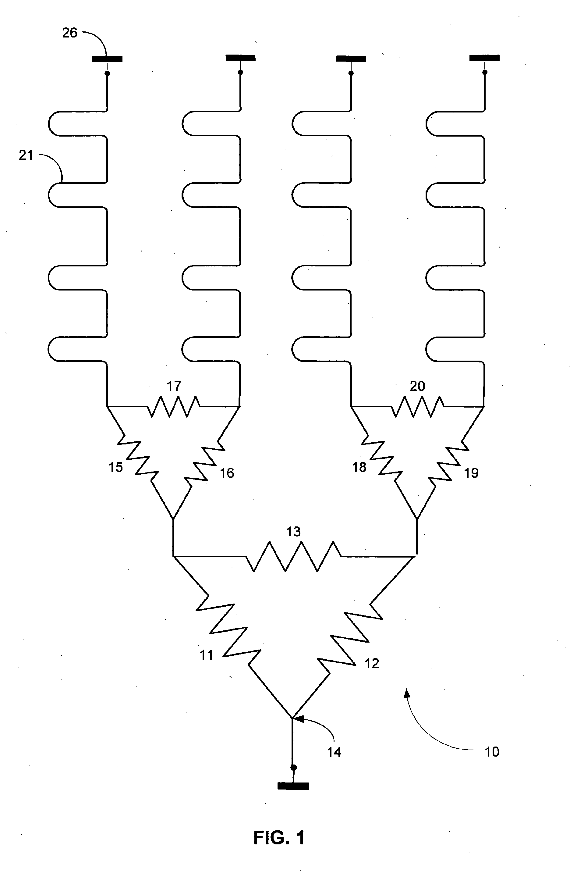
[0060]FIG. 1 shows a simple calibration signal injection network 10 having a triad of dividers 11, 12 and 13 interconnected so that a common junction of the dividers 11 and 12 s...


PUM


Abstract

A phased antenna arrangement and a method for estimating the calibration ratio of an active phased antenna having a plurality of phased array antenna elements are described. The phased antenna arrangement includes a plurality of antenna elements, a plurality of receiving channels, an injection unit for injection of calibrating signals into the receiving channels, a point RF-source, located in a far field zone, a distance measurement unit, an amplitude and phase measurement unit and a data processing unit. The method comprises injecting an internal calibrating signal having a known amplitude and phase to each antenna element. An external calibration signal from a stationary RF-source is sequentially injected to all of the phased array antenna elements so that different phases of the external calibration signal arrive at each of the antenna elements. The differences in phases of the external calibration signal reaching the antenna elements are compensated so as compute an effective signal amplitude that would reach all of the antenna elements at zero phase difference. Calibration ratio is calculated as the ratio between the amplitude of the internal calibrating signal to the effective signal amplitude of the external calibration signal.

Description

FIELD OF THE INVENTION[0001]This invention relates to phased array antennas and in particular to calibration of phased array antennas having field calibration capability.BACKGROUND OF THE INVENTION[0002]The antenna of an active phased array system must be able to steer its beam so that the system can obtain information about the surroundings in different directions. It is also desirable that the antenna suppress signals from other directions than the direction in which the system is currently transmitting and receiving. A phased array antenna comprises a number transmitting / receiving elements, usually arranged in a planar configuration. Each element, or a group of elements, is driven by a transmit / -receive (T / R) module which controls the phase and the amplitude of the corresponding antenna element.[0003]On transmission of a signal from a phased array antenna, the signal is divided into a number of sub-signals, and each sub-signal is fed to one of the modules. The modules comprise si...

Claims


Application Information

Patent Timeline
IPC IPC(8): G01S7/40
CPCH01Q3/267
Inventor LOMES, ALEXANDERVAGMAN, YACOVREICHMAN, HAIM
Owner ELTA SYST LTD
Why Eureka
Try Eureka