Powerline carrier zero-crossing transformer mapping with asymmetric RF return path

a technology of asymmetric return path and powerline carrier, applied in powerline communications applications, wireless systems/telephones, instruments, etc., can solve the problems of not being able to dynamically change the back office system and diminish the load on the transformer

Active Publication Date: 2011-05-26
SILVER SPRING NETWORKS
View PDF6 Cites 66 Cited by
  • Summary
  • Abstract
  • Description
  • Claims
  • Application Information

AI Technical Summary

Benefits of technology

The present invention allows for mapping out the layout of a utility distribution network by using a wireless mesh network. This helps identify which parts of the system are connected to specific locations on the map. Each part of the system has its own monitoring device called a communication node or NIC, which sends signals through the power lines back to the main control center. These signals help determine who needs what kind of maintenance or replacement. Overall, this technology makes it easier to manage and maintain the infrastructure of our energy systems more efficiently.

Problems solved by technology

This patent discusses how advanced metering infrastructure networks use wireless meshes to send data between the backend system of a utility and meters installed at customers' homes. However, the layout of these networks doesn't always match up with the actual physical distribution network used to carry electrical energy to clients. One problem addressed in the patent is the difficulty of monitoring conditions like temperatures and currents at certain points in the network, which would allow the utility to better manage its distribution of electricity.

Method used


Image

  • Powerline carrier zero-crossing transformer mapping with asymmetric RF return path
  • Powerline carrier zero-crossing transformer mapping with asymmetric RF return path
  • Powerline carrier zero-crossing transformer mapping with asymmetric RF return path

Examples


Embodiment Construction

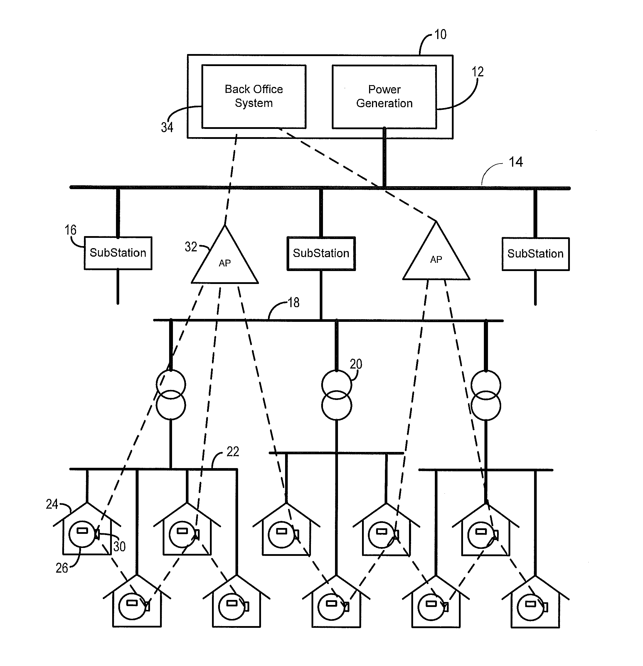
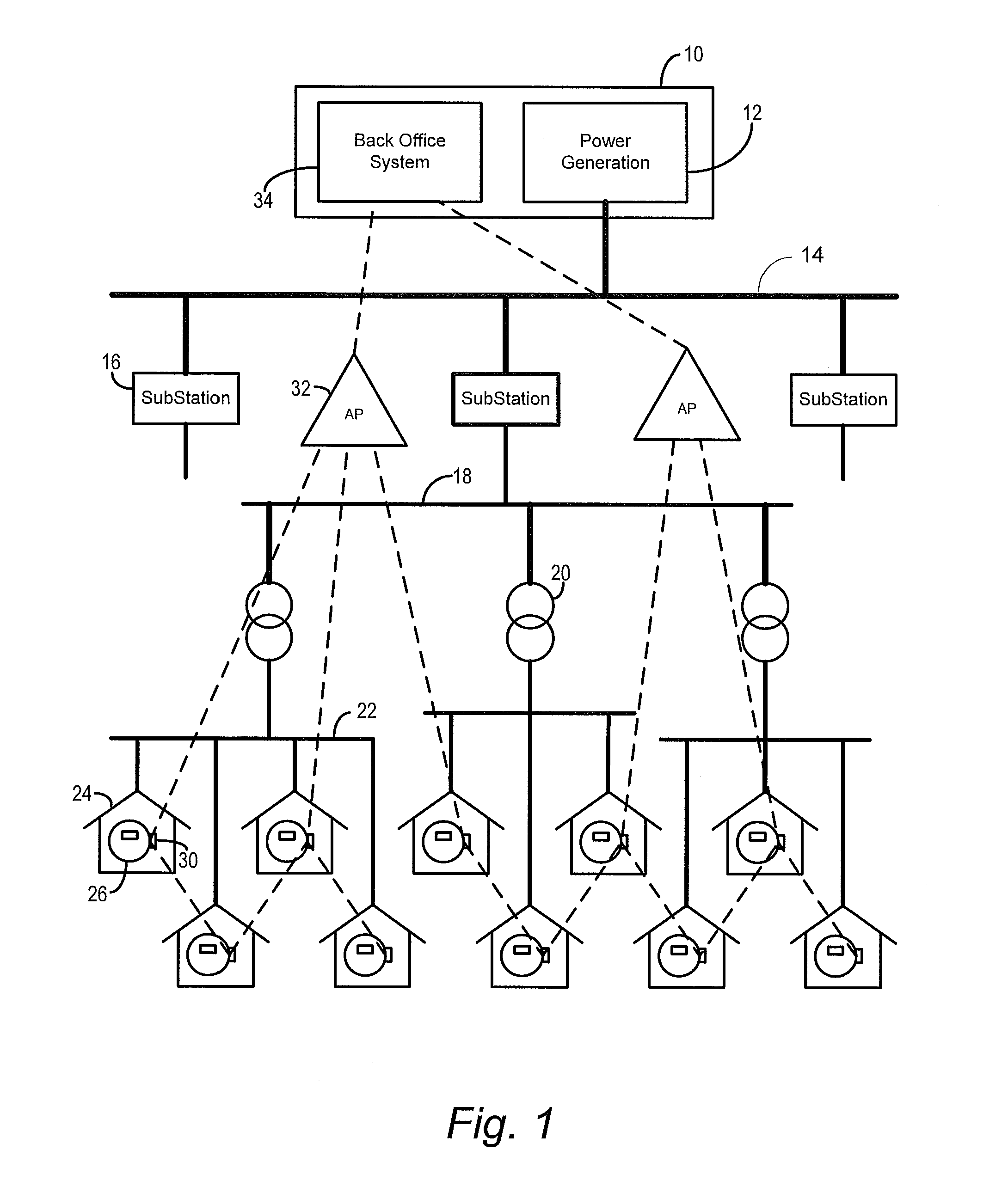
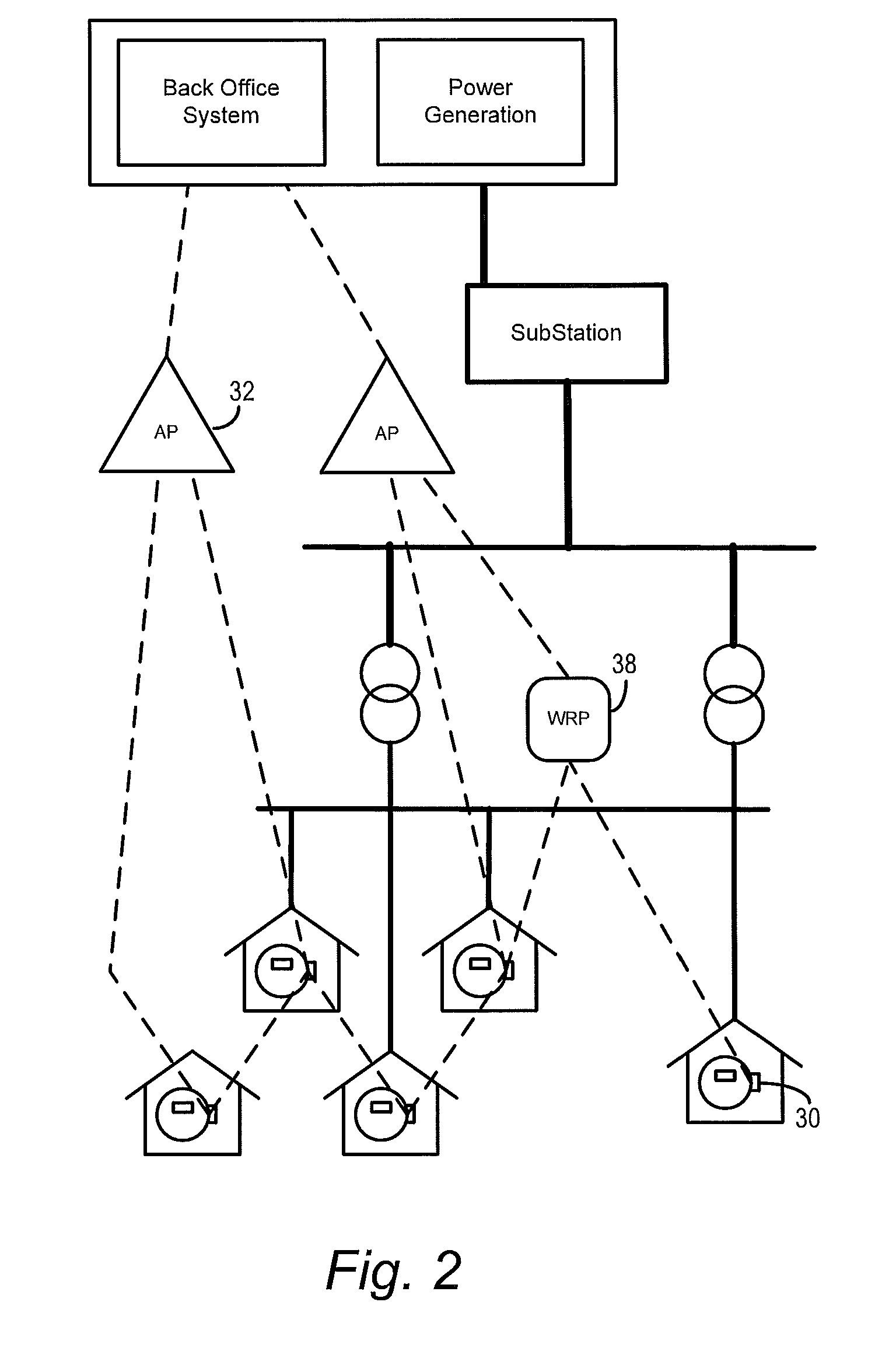
[0020]The invention described herein provides mechanisms to discover and enable the mapping of the correspondence between a utility distribution network topology and an RF mesh data communication network topology. This disclosure provides an exemplary implementation by which RF mesh data communication networks can identify utility distribution topologies by using simple, cost-effective 1-way power line communications combined with mesh networking data communication to identify and map transformers and other distribution equipment to a back office system network server.

[0021]To facilitate an understanding of the concepts upon which the invention is based, they are described hereinafter with reference to exemplary embodiments implemented using wireless networks that utilize RF mesh networking techniques. However, it will be appreciated that these concepts can also be implemented in other types of data networks that utilize different modulation and / or transmission techniques.

[0022]More...


PUM


Abstract

Techniques are disclosed by which RF mesh networks can identify utility distribution topologies by using power line communication combined with wireless networking to identify the mapping of transformers and other distribution equipment at a back office system server. At a specified time, an item of distribution equipment signals a unique identifier by introducing a phase shift in the electric power being delivered by that equipment. A meter node detects and decodes these temporal shifts to obtain an identifier of equipment supplying the power to it. Upon ascertaining this identification, the meter node sends an acknowledgment to thereby register with that equipment. The association of the particular customer's premises with the equipment is also sent to a back office system, to enable a map of the correspondence between meter and the equipment to be generated.

Description


Claims


Application Information

Patent Timeline
Owner SILVER SPRING NETWORKS
Why Eureka
Try Eureka