Method and apparatus of receiving data in wireless communication system

Active Publication Date: 2011-05-26
LG ELECTRONICS INC
View PDF6 Cites 111 Cited by
  • Summary
  • Abstract
  • Description
  • Claims
  • Application Information

AI Technical Summary

Benefits of technology

[0022]A method and an apparatus of effectively receivin

Problems solved by technology

If the UE cannot correctly detect the control information of the UE from the pieces of multiplexed control information, user data on the data channel cannot be decoded.
However,

Method used


Image

  • Method and apparatus of receiving data in wireless communication system
  • Method and apparatus of receiving data in wireless communication system
  • Method and apparatus of receiving data in wireless communication system

Examples


Example

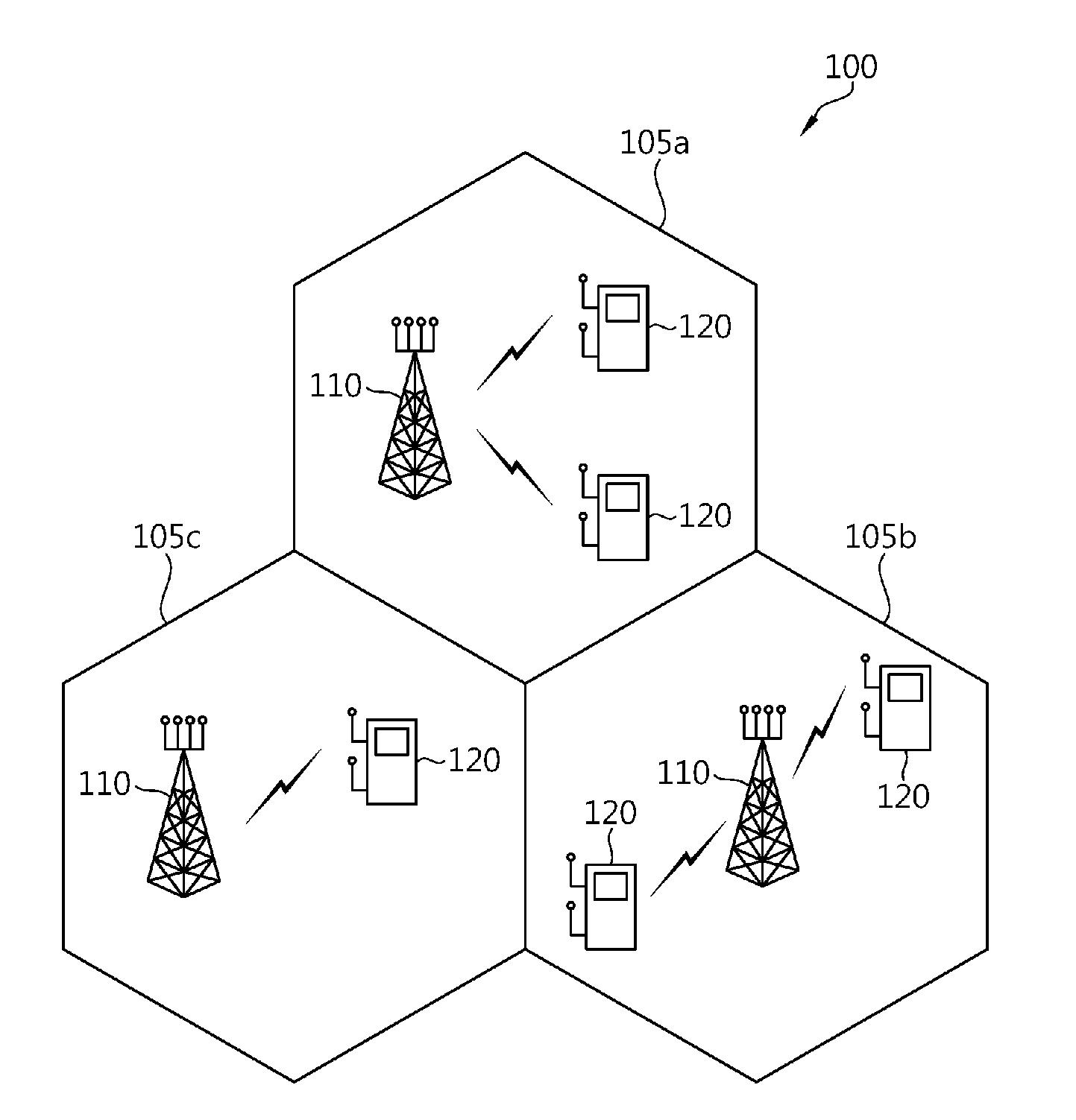
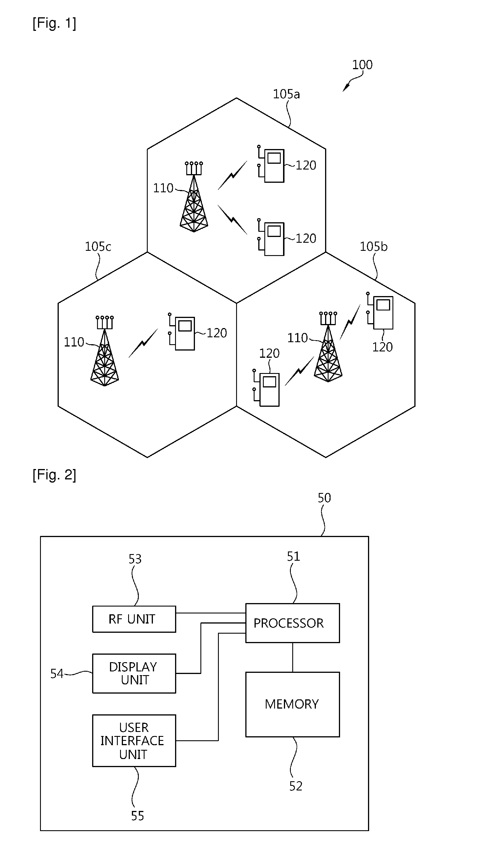
[0041]FIG. 1 is a block diagram showing a wireless communication system.

[0042]Referring to FIG. 1, a wireless communication system 100 includes at least one base station (BS) 110. The BSs 110 provide communication services with respect to specific geographical regions (generally referred to as cells) 105a, 105b, and 105c. Each cell can be divided into a plurality of regions (referred to as sectors). A user equipment (UE) 120 may be fixed or mobile, and may be referred to as another terminology, such as a mobile station (MS), a user terminal (UT), a subscriber station (SS), a wireless device, etc. The BS 110 is generally a fixed station that communicates with the UE 120 and may be referred to as another terminology, such as an evolved node-B (eNB), a base transceiver system (BTS), an access point, etc.

[0043]Hereinafter, downlink means communication from the BS 110 to the UE 120, and uplink means communication from the UE 120 to the BS 110. In downlink, a transmitter may be a part of ...


PUM


Abstract

A method and an apparatus of receiving data in a wireless communication system are provided. The method includes detecting a physical downlink control channel (PDCCH) on which control information is transmitted in a first subframe, and receiving data in at least one second subframe based on the control information.

Description

TECHNICAL FIELD[0001]The present invention relates to wireless communications, and more particularly, to a method and an apparatus of receiving data in a wireless communication system.BACKGROUND ART[0002]In wireless communication systems, one base station (BS) generally provides services to a plurality of user equipments (UEs). The BS schedules user data for the plurality of UEs, and transmits the user data together with control information containing scheduling information for the user data. In general, a channel for carrying the control information is referred to as a control channel, and a channel for carrying the user data is referred to as a data channel. The UE finds control information of the UE by searching for the control channel, and processes data of the UE by using the control information.[0003]In order for the UE to receive user data assigned to the UE, control information for the user data on a control channel must be received. In a given bandwidth, a plurality of piec...

Claims


Application Information

Patent Timeline
IPC IPC(8): H04W40/00
CPCH04J11/0069Y02B60/50H04W48/12H04W28/06Y02D30/70H04L1/001
Inventor LEE, MOON ILKIM, SO YEONCHUNG, JAE HOONKO, HYUN SOOHAN, SEUNG HEE
Owner LG ELECTRONICS INC
Why Eureka
Try Eureka