
Optical router with nearly ideal performance

a technology of optical routers and routers, applied in the field of optical frequency routers, can solve the problems of narrow bandwidth, inability to design, and large size, and achieve the effects of improving transmission properties, reducing size, and increasing the number of channels

Active Publication Date: 2011-05-26
DRAGONE CORRADO PIETRO
View PDF13 Cites 1 Cited by
  • Summary
  • Abstract
  • Description
  • Claims
  • Application Information

AI Technical Summary

Benefits of technology

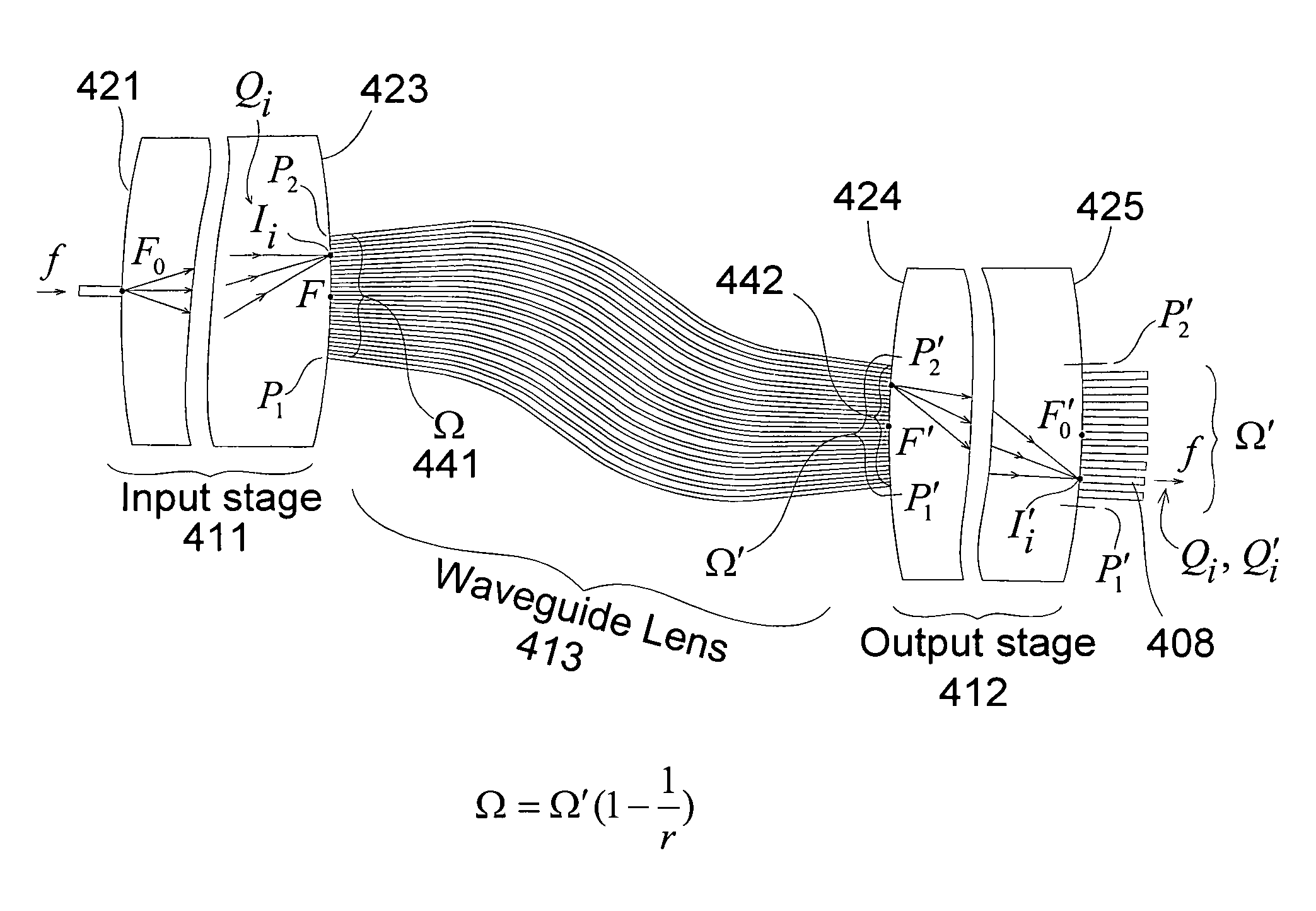
[0005]The primary objective of the present invention is the realization of an optical router with improved transmission properties, reduced size, increased number of channels and maximally flat passbands. The new router is an optimized imaging arrangement including two waveguide gratings, having opposite dispersions, nearly identical free-spectral ranges, and a waveguide lens connected between the two gratings.
[0006]In one embodiment, the router transmission coefficients, from a particular input waveguide to the various output waveguides, are all characterized by different orders of the two gratings. In a second embodiment, a composite lens is used between the two gratings to substantially reduce the loss caused by secondary images produced by the first grating. The composite lens has a single input aperture and three separate output apertures separated by suitable matching gaps. Significant advantages of increased number of channels and improved performance are realized in both cases.

Problems solved by technology

However, an undesirable feature of this router is its narrow bandwidth, caused by the strong wavelength dependence of each image location produced by the grating.
However, an undesirable feature of this imaging arrangement is its large size.
In particular, the second patent requires between the two gratings many waveguide lenses, one for each output waveguide, and therefore this design is only feasible if the number N of output waveguides is small.
On the other hand, only one lens is required by the third patent, but an undesirable feature in this case is that the output waveguides are widely spaced (as shown in a following section) and this increases again the size of the router.

Method used


Image

  • Optical router with nearly ideal performance
  • Optical router with nearly ideal performance
  • Optical router with nearly ideal performance

Examples


Embodiment Construction

[0018]Waveguide Grating Router

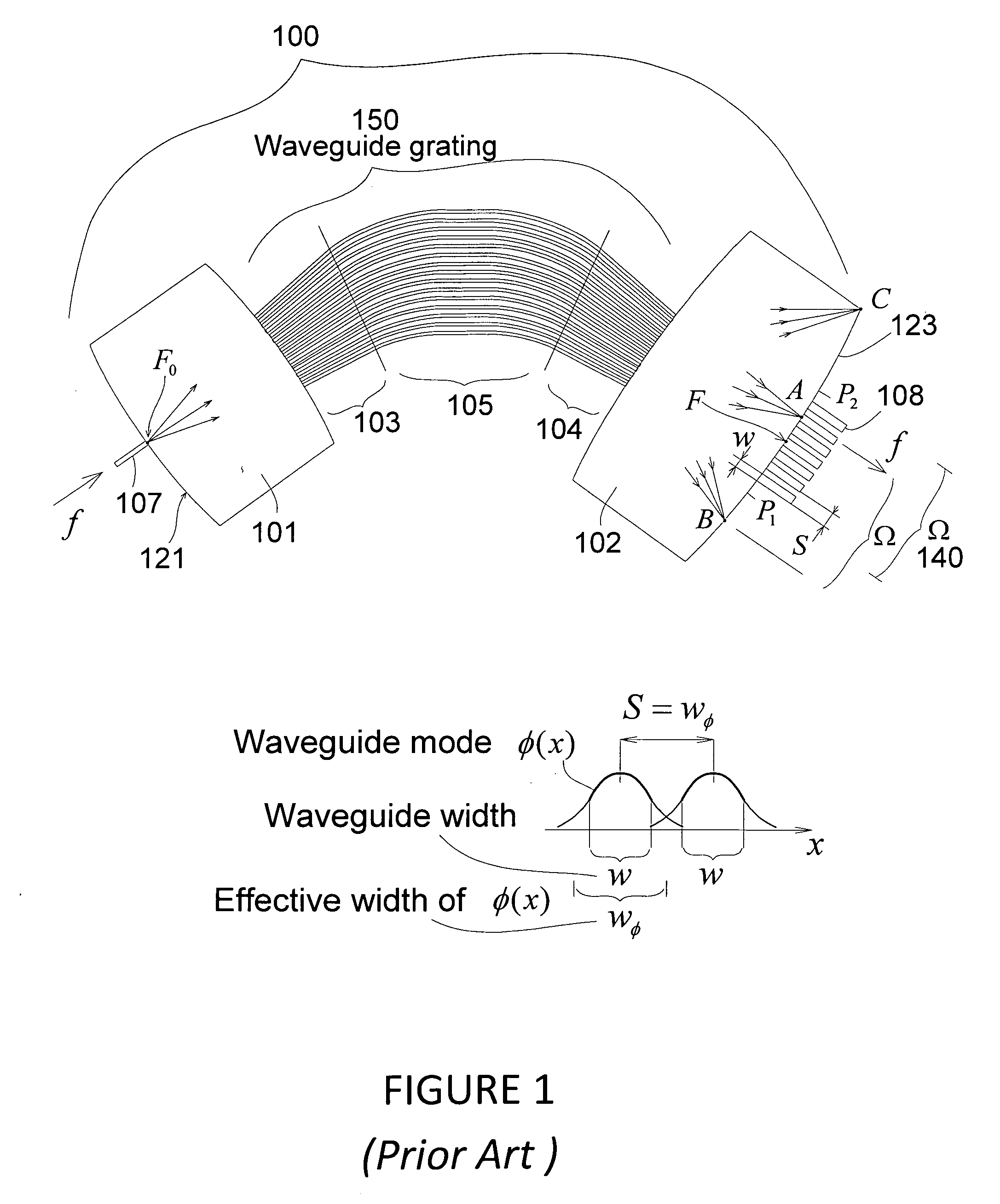
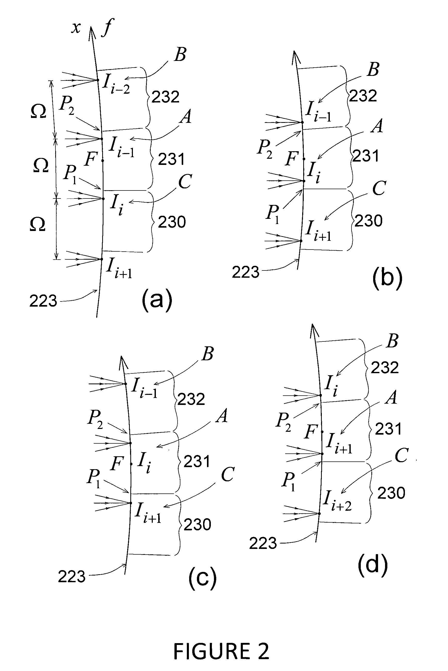
[0019]FIG. 1 shows the basic structure of a prior art imaging arrangement 100 of the type used in this invention. Note the imaging arrangement will also be referred to herein as a router. The imaging arrangement 100 is described in U.S. Pat. No. 5,002,350, issued on Mar. 26, 1991, and U.S. Pat. No. 5,136,671, issued on Aug. 4, 1992, The imaging arrangement 100 includes an input section 101 and an output section 102 spaced apart and interconnected by a grating 150 consisting of an appropriate plurality of optical waveguide arms 105 connected between two periodic arrays 103,104 of radial waveguides. The input and output sections typically are each free-space slabs, such as star couplers, and the arrangement has the property that wave energy applied by an input waveguide 107 acting as a point source forms a plurality of output images, of which three are shown as A, B, C in FIG. 1. The optical waveguide arms 105 typically are thin narrow layers (planar stri...


PUM


Abstract

An optimized planar optical router consisting of two stages performing stationary imaging between an input waveguide and a set of output waveguides has advantages of reduced size, larger number of channels and minimal loss variation in each passband. Each stage is a waveguide grating router, the two stages are characterized by nearly equal free-spectral ranges, and a waveguide lens is connected between the two stages. In one embodiment, the lens is connected between the central zones of the two stages, and the diffraction orders of the two stages vary monotonically from each passband to the next. In another embodiment, the loss caused by secondary images is substantially reduced by using a composite lens providing efficient transmission of both principal and secondary images.

Description

FIELD OF THE INVENTION[0001]This invention relates to optical frequency routers in optical systems and, more particularly, to optical routers with maximally flat passbands.BACKGROUND OF THE INVENTION[0002]An important function that must be provided in optical networks is wavelength routing. In particular, wavelength routing is needed at each node, in order to combine and separate different wavelength channels. Typically, the router is realized in integrated form by using a waveguide grating, and an example is shown in FIG. 1. The router in this example only includes one input waveguide and its purpose is to separate the input channels, and transmit them to different output waveguides. The waveguide grating simply transforms each input signal, intended for a particular output waveguide, into a corresponding output image produced (approximately) at the output waveguide location. However, an undesirable feature of this router is its narrow bandwidth, caused by the strong wavelength dep...

Claims


Application Information

Patent Timeline
IPC IPC(8): G02B6/28
CPCG02B6/12021
Inventor DRAGONE, CORRADO PIETRO
Owner DRAGONE CORRADO PIETRO
Learn More