Variable displacement pump

a variable-discharge pump and pump technology, applied in the direction of machines/engines, rotary/oscillating piston pump components, liquid fuel engines, etc., can solve the problems of excessive pump discharge during operation and waste of energy, and achieve the effect of suppressing an excessive pump discharg

Active Publication Date: 2011-05-26
HITACHI ASTEMO LTD
View PDF5 Cites 37 Cited by
  • Summary
  • Abstract
  • Description
  • Claims
  • Application Information

AI Technical Summary

Benefits of technology

[0005]It is, therefore, in view of the previously-described disadvantages of the prior art, an object of the invention to provide a variable displacement pump configured to appropriately suppress an excessive rise in the discharge of the pump even during operation at high pump revolution speeds.

Problems solved by technology

Thus, there is a possibility of an excessive discharge of the pump during operation at high pump revolution speeds.
This leads to the problem of wasteful energy consumption.

Method used


Image

  • Variable displacement pump
  • Variable displacement pump
  • Variable displacement pump

Examples


first embodiment

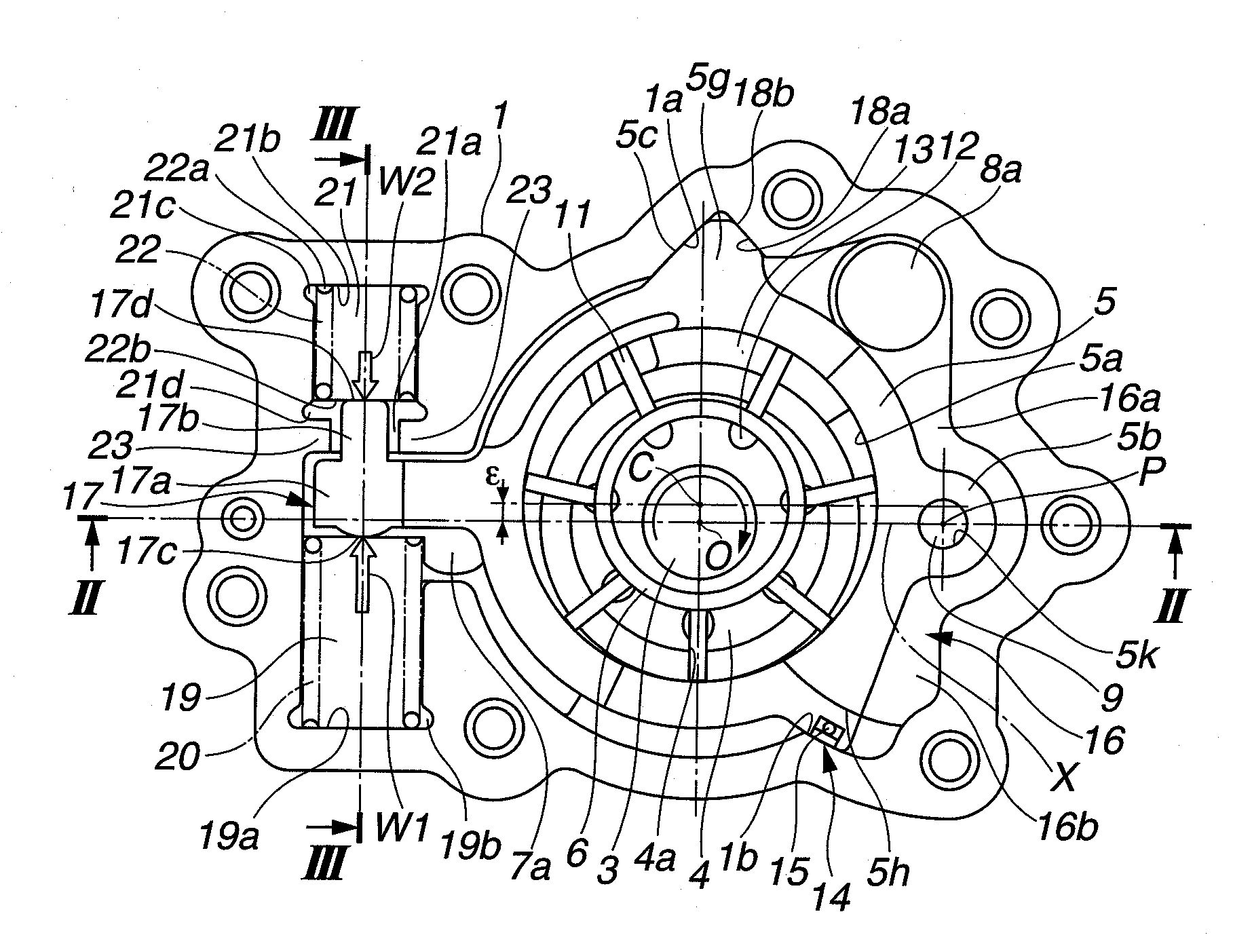
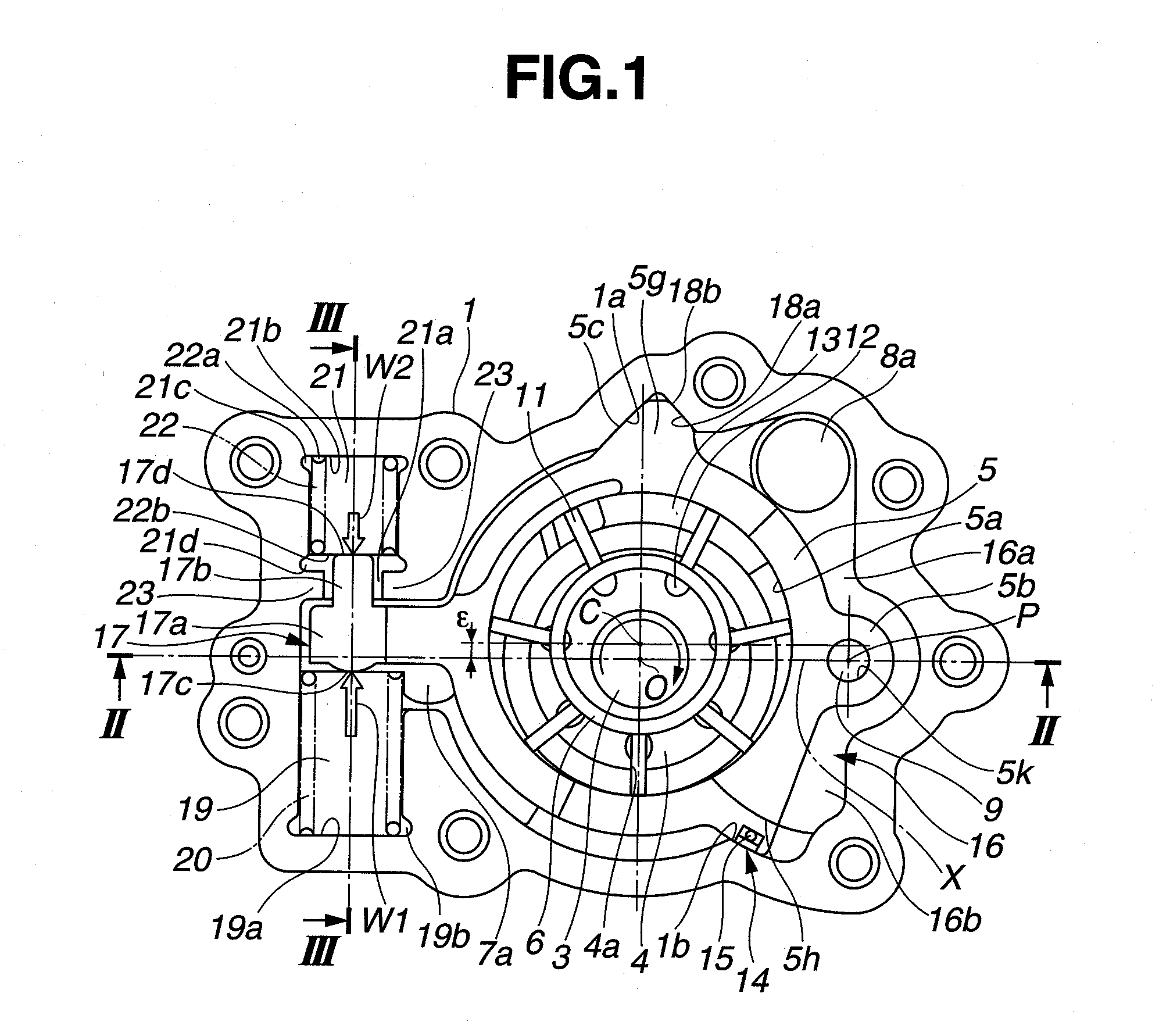
[0022]Referring now to the drawings, particularly to FIGS. 1-6, the variable displacement pump of the first embodiment is applied to an internal combustion engine of an automotive vehicle, for supplying moving engine parts with lubricating oil and for delivering oil (serving as a working medium as well as a lubricating substance) to a variable valve actuation device, which is installed for variably controlling engine valve operating characteristics of an internal combustion engine. The variable displacement pump of the first embodiment is exemplified in a vane type variable displacement rotary pump and installed on the front end of a cylinder block of the internal combustion engine. As shown in FIGS. 1-2, the variable displacement pump of the first embodiment is comprised of a pump housing 1, a pump cover 2, a drive shaft 3, a vane rotor 4, a cam ring (a movable member) 5, and a pair of vane rings 6, 6. Pump housing 1 is formed into a substantially cylindrical shape and closed at on...

second embodiment

[0083]Referring now to FIGS. 9-10, there is shown the variable displacement pump of the second embodiment. As can be seen from comparison between the pump configuration of FIGS. 1 and 4 (the first embodiment) and the pump configuration of FIGS. 9-10 (the second embodiment), the basic pump configurations are the same in the first and second embodiments. However, the structure of the fulcrum of oscillating motion of cam ring 5 and the structure of control oil chamber 16 of the second embodiment (see FIGS. 9-10) differ from those of the first embodiment.

[0084]As best seen in FIG. 9, as a fulcrum of oscillating motion of cam ring 5, the second embodiment uses a pivot portion 5i of the cam ring side and a pivot groove 1g of the pump housing side, without utilizing pivot pin 9. Pivot portion 5i is formed integral with the outer periphery of cam ring 5, facing the control oil chamber 16, and formed as a substantially semi-circular protrusion. Pivot groove 1g is recessed in the inner periph...

third embodiment

[0090]Referring now to FIGS. 11-12, there is shown the variable displacement pump of the third embodiment. As can be seen from comparison between the pump configuration of FIGS. 1 and 4 (the first embodiment) and the pump configuration of FIGS. 11-12 (the third embodiment), the basic pump configurations are the same in the first and third embodiments. However, the installation locations of first and second coil springs 20 and 22 of the third embodiment (see FIGS. 11-12) differ from those of the first embodiment.

[0091]As seen in FIGS. 11-12, first spring chamber 19 is located at an angular position (see the direction of 4 o'clock) substantially corresponding to the second oil control chamber 16b, whereas second spring chamber 21 is located at an angular position (see the direction of 12 o'clock) corresponding to the topside of pump housing 1.

[0092]The bottom face (i.e., the right-hand end face of first coil spring 20, viewing FIG. 11) of first coil spring 20, accommodated in first sp...


PUM


Abstract

A variable displacement pump includes a pump structural member configured to change volumes of a plurality of working chambers by rotation of a rotor, so as to introduce oil through an inlet port into the working chambers and to discharge the oil through a discharge port, and further configured to oscillate a cam ring by a discharge pressure introduced into a control oil chamber. A first coil spring is provided to force the cam ring in a direction for increasing of a rate of change of the working-chamber volume. A second coil spring is provided to force the cam ring in a direction for decreasing of the rate of change of the working-chamber volume. The first and second coil springs are laid out on both sides of an arm portion of the cam ring in a manner so as to be opposed to each other.

Description

TECHNICAL FIELD[0001]The present invention relates to a variable displacement pump that supplies a variable valve actuation device configured to control engine-valve operating characteristics, moving engine parts of an automotive vehicle and the like, with oil.BACKGROUND ART[0002]In recent years, there have been proposed and developed various variable displacement pumps capable of varying a discharge of working fluid, usually expressed as a fluid flow rate per one revolution of a pump rotor. A variable displacement pump of this type has been disclosed in Japanese Patent Provisional Publication No. 2009-92023 (hereinafter is referred to as “JP2009-092023”) assigned to the assignee of the present invention. In the variable displacement vane pump disclosed in JP2009-092023, its discharge is variably adjusted by changing an eccentricity of the geometric center of a cylinder bore of a cam ring with respect to the axis of rotation of a vane rotor. One end of the cam ring is pivoted on a p...

Claims


Application Information

Patent Timeline
Patent Type & Authority Applications(United States)
IPC IPC(8): F01C20/18
CPCF04C2/3442F04C14/226F04C2270/14F04C2270/12F04C15/0049
Inventor SAGA, KOJIOHNISHI, HIDEAKIWATANABE, YASUSHI
Owner HITACHI ASTEMO LTD
Why Eureka
Try Eureka