Eureka AIR delivers breakthrough ideas for toughest innovation challenges, trusted by R&D personnel around the world.

Power Transmission Mechanism for an Electric Bicycle

Inactive Publication Date: 2011-05-26
SONG KANG YOUNG
View PDF12 Cites 18 Cited by
  • Summary
  • Abstract
  • Description
  • Claims
  • Application Information

AI Technical Summary

Benefits of technology

[0007]The first purpose of the present invention is to provide a power transmission mechanism for an electric bicycle which selectively transmits motor power or pressing power onto pedal to the crank without interference between them to run the electric bicycle and changes a general bicycle into the electric bicycle by its simple installation thereon.
[0008]The second purpose of the present invention is to provide a power transmission mechanism for an electric bicycle the parts of which are not massed on the driving sprocket side and divided onto the both sides with center of the crank shaft housing so that its installation on the bicycle becomes easy and installation of a transmission for shifting gear ratio becomes easy too.
[0028]According to the present invention, only two one-way clutches are used to transmit the motor power and the pressing power onto the pedal to the driving sprocket without the interference between the powers so that the electric bicycle runs only by the motor power or only by the pressing power onto the pedal or the resultant power of them. Also, a rider can rest putting his or her feet on the pedals or pressing the pedals in the reverse direction when the electric bicycle runs by the motor power. In this case, the power is transmitted to the driving sprocket so that the transmission efficiency is high and the electricity is less consumed.
[0029]Also, when the electric bicycle runs only by the pressing power onto the pedal, the pressing of the pedals is easy as the general bicycle.
[0031]Especially, according to the second aspect of the present invention, a driving motor connection one-way clutch which receives power from the driving motor is arranged at the opposite side of the driving sprocket side with center of the crank shaft housing so that the installation of the power transmission mechanism becomes easy and convenient. Also, a transmission for shifting gear ratio can be easily installed.

Problems solved by technology

Also, pressing the pedal is hard unlike a general bicycle because of the high friction and it is hard to run only by the pressing power onto the pedal, the motor power being turned off.
Accordingly, when a battery is exhausted or the rider wants to run the electric bicycle by his or her press onto the pedal, the running is not easy.
If the motor is installed on the driving sprocket side, chain for transmitting the power from the motor may interfere with the driving sprocket mechanism and it is hard to install the motor and a transmission as well.

Method used


Image

  • Power Transmission Mechanism for an Electric Bicycle
  • Power Transmission Mechanism for an Electric Bicycle
  • Power Transmission Mechanism for an Electric Bicycle

Examples


Embodiment Construction

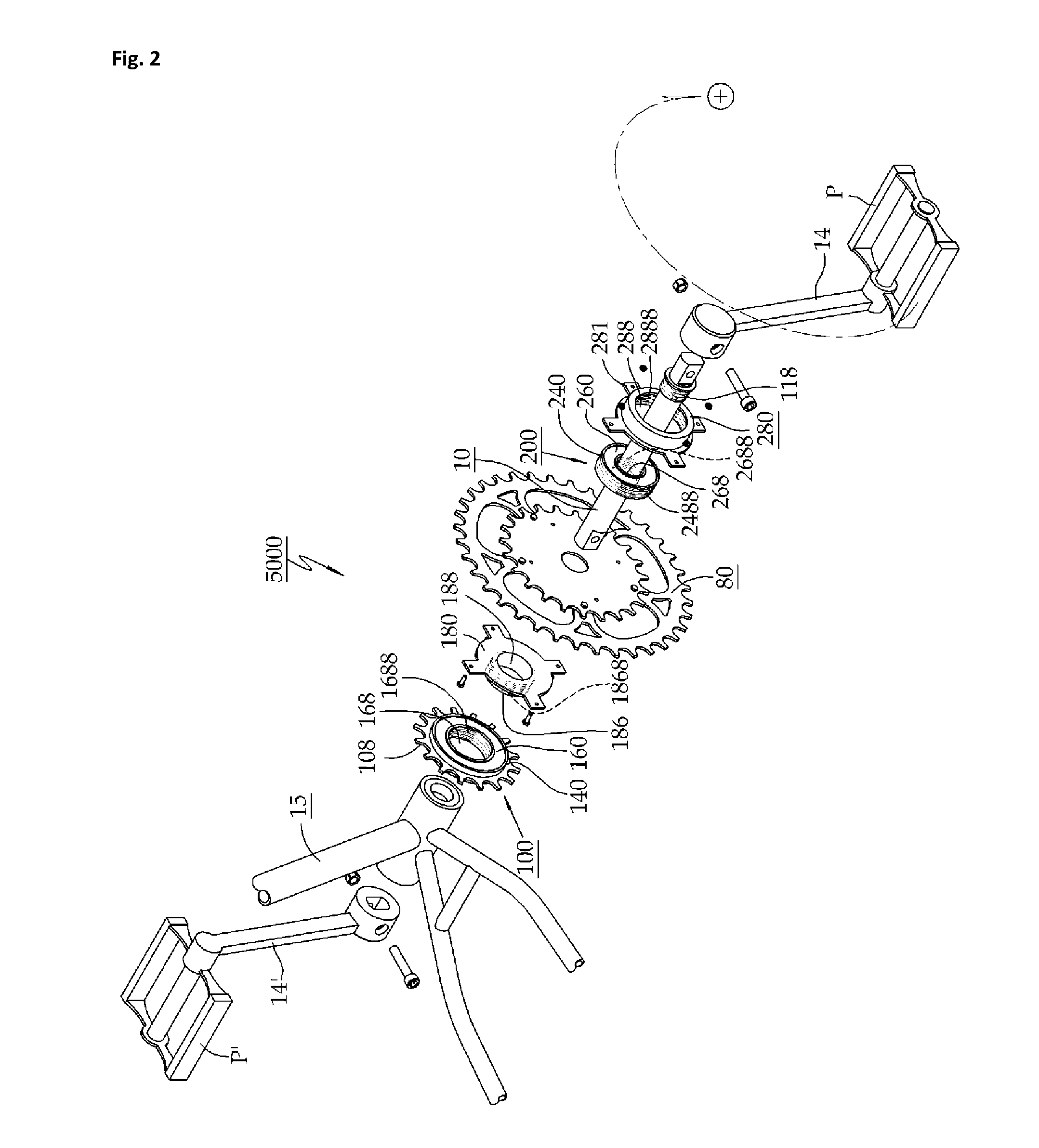
[0041]FIGS. 1 to 7 show a power transmission mechanism according to the first aspect of the present invention. FIGS. 8 to 15 show a power transmission mechanism according to the second aspect of the present invention. The power transmission mechanism according to the first aspect or the second aspect of the invention is indicated by the same numeral 5000.

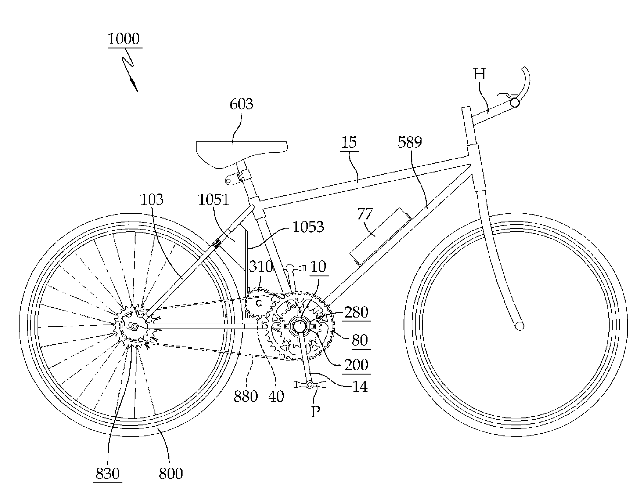
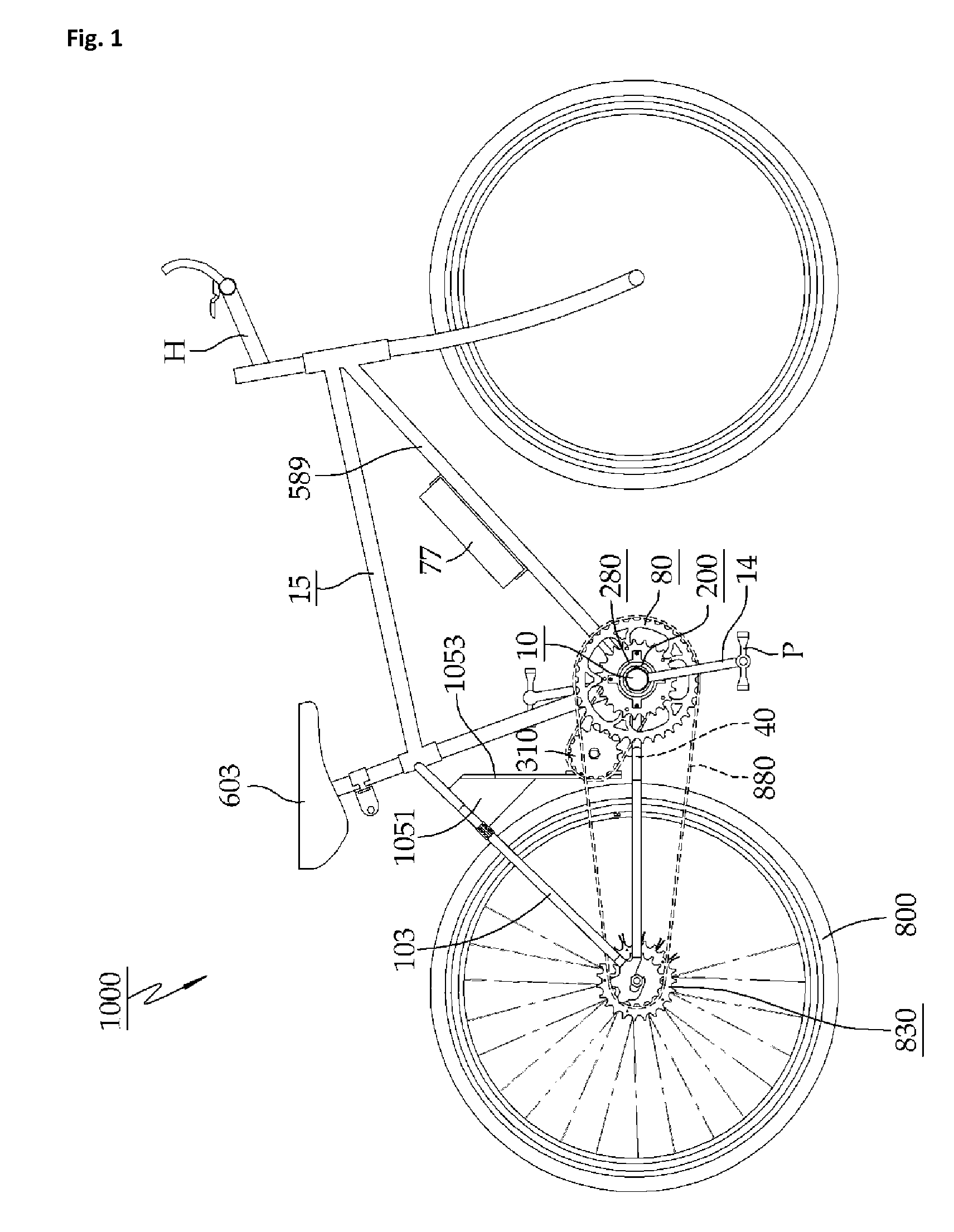
[0042]Firstly, FIG. 1 shows an electric bicycle 1000 on which the power transmission mechanism 5000 according to the first aspect of the present invention is mounted. As described later, if the power transmission mechanism 5000 is mounted on a bicycle, the bicycle will be an electric bicycle and the power transmission mechanism 5000 is very easy to be mounted on the bicycle because its constitution is simple.

[0043]There shows a crank shaft 10 centering a driving sprocket 80 and a crank arm 14 is connected with the crank shaft 10 and a pedal P is equipped with the crank arm 14. The driving sprocket 80 is connected with a hub sprocket...


PUM


Abstract

A power transmission mechanism 5000 for an electric bicycle has a driving motor 990 mounted on the bicycle, and an outer shaft 580 with a hollow interior through which a crankshaft 590 of the bicycle penetrates. The outer shaft 580 is coupled to a driving sprocket 50 of the bicycle via an outer shaft combiner 18. The driving transmission mechanism 5000 of the electric bicycle has a driving motor connection one-way clutch 300 and a pedal connection one-way clutch 200.

Description

BACKGROUND OF THE INVENTION[0001]The present invention relates to a power transmission mechanism for an electric bicycle and, more particularly to the power transmission mechanism for an electric bicycle which enhances the electric bicycle to run by motor power or by pressing power onto a pedal, respectively, or by resultant power of them. The present invention minimizes the power transmission loss to transmit the power efficiently and makes it possible to use selectively the motor power and the pressing power onto the pedal so that the rider can run the electric bicycle the most conveniently and the most comfortably.[0002]Generally, an electric bicycle uses a hub motor to drive the rear wheel. In the electric bicycle using the hub motor, the friction between the driving part of the motor and the hub is high and the power transmission efficiency falls down. Also, pressing the pedal is hard unlike a general bicycle because of the high friction and it is hard to run only by the pressi...

Claims


Application Information

Patent Timeline
IPC IPC(8): B62M6/55
CPCB62M6/55B62M6/90
Inventor SONG, KANG YOUNG
Owner SONG KANG YOUNG
Why Eureka
Eureka Blog
Learn More