Common rail fuel pump with combined discharge and overpressure relief valves

a fuel pump and common rail technology, applied in the direction of liquid fuel engines, piston pumps, positive displacement liquid engines, etc., can solve the problems of high cost, difficult pre-testing of sub-assembly, and the valve within the housing suffers, so as to improve the flexibility of the radial location of the outlet fitting, the effect of reducing the system cos

Active Publication Date: 2011-06-02
STANDYNE INC
View PDF29 Cites 88 Cited by
  • Summary
  • Abstract
  • Description
  • Claims
  • Application Information

AI Technical Summary

Benefits of technology

[0004]According to an aspect of the present invention, the outlet check valve and the pressure relief valve are contained within a single fitting of the high pressure fuel pump. The advantages includ

Problems solved by technology

The conventional configuration of separate outlet check valve and pressure relief valve within the housing suffers from several disadv

Method used


Image

  • Common rail fuel pump with combined discharge and overpressure relief valves
  • Common rail fuel pump with combined discharge and overpressure relief valves
  • Common rail fuel pump with combined discharge and overpressure relief valves

Examples


Embodiment Construction

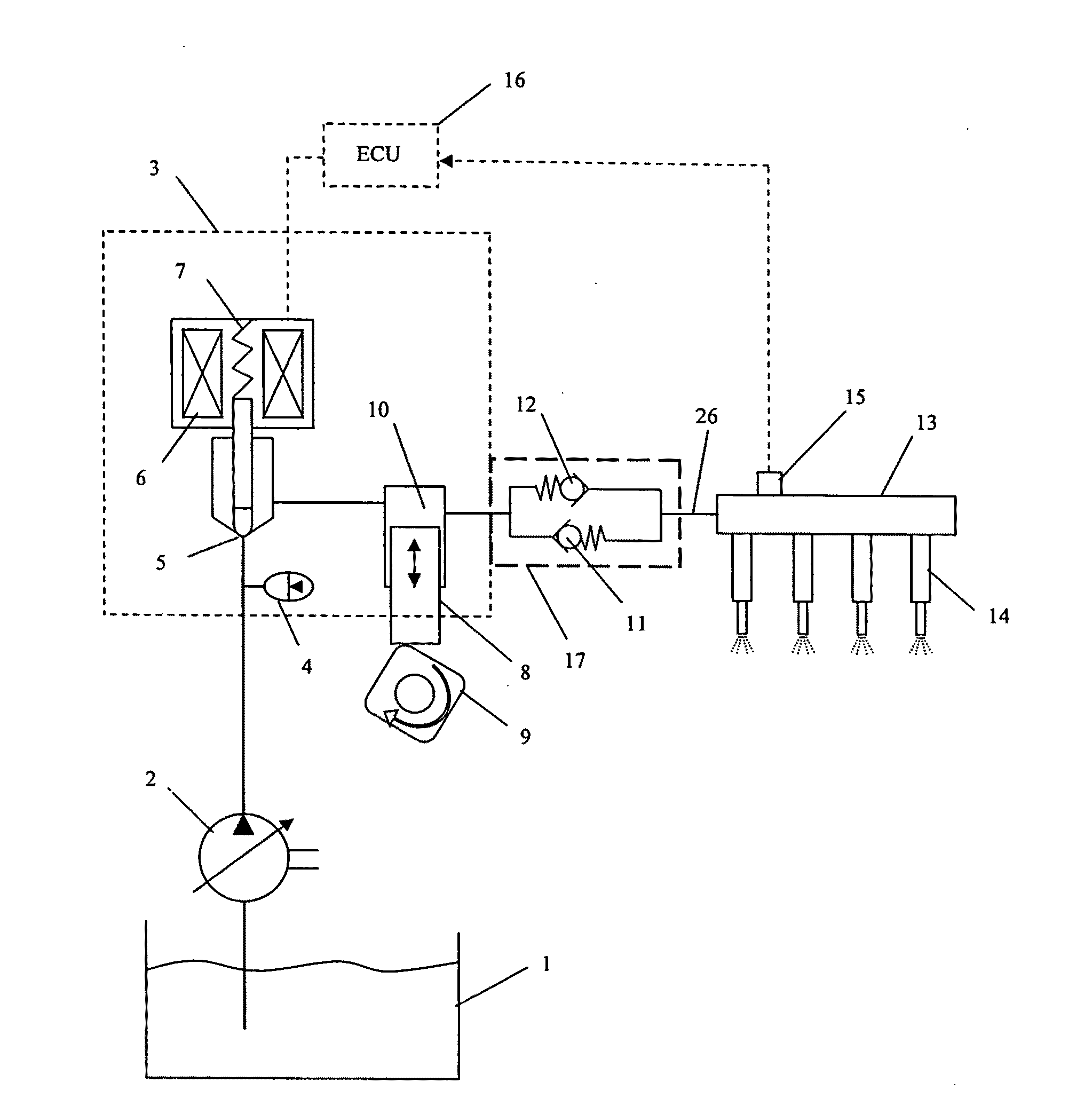
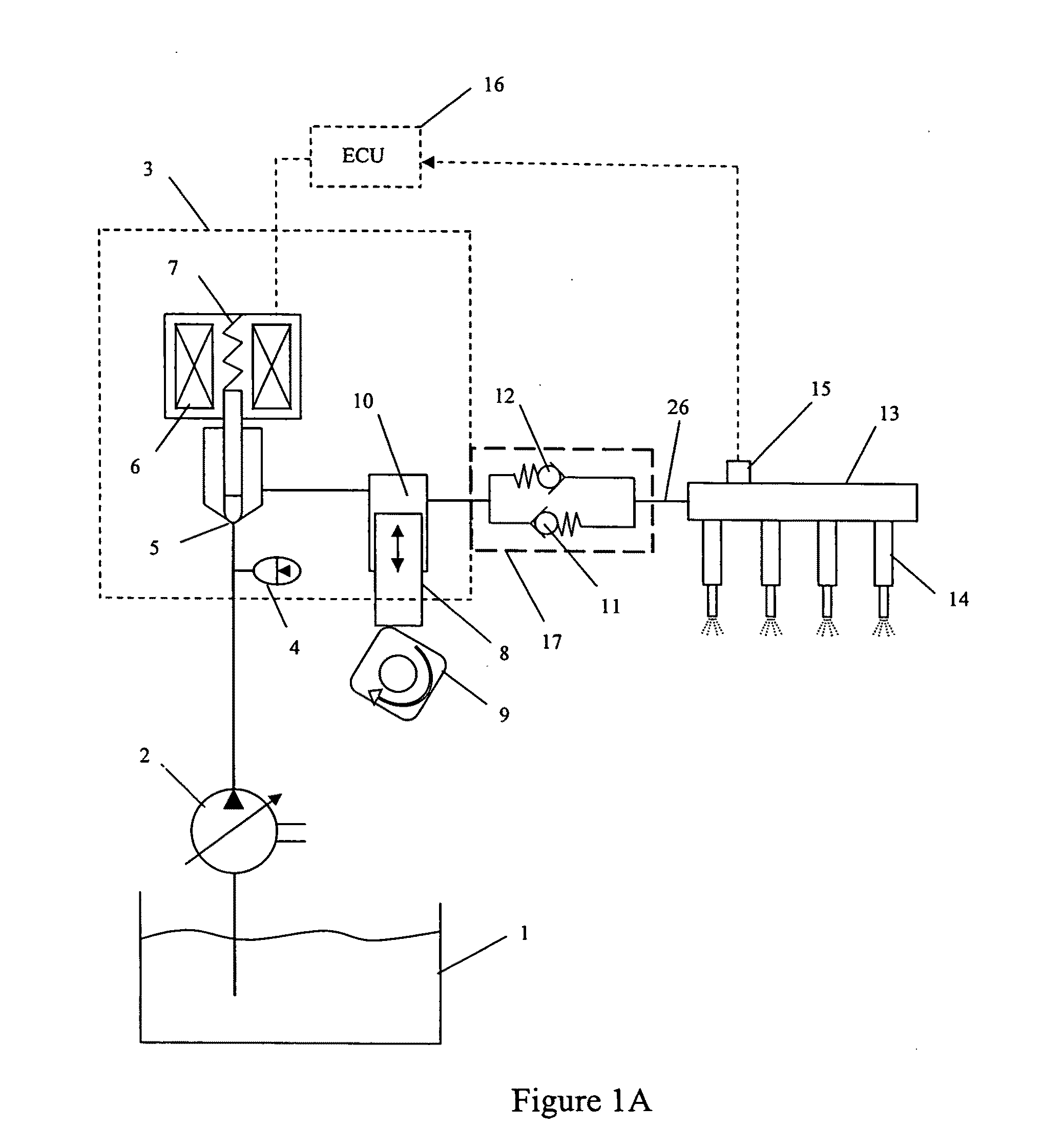
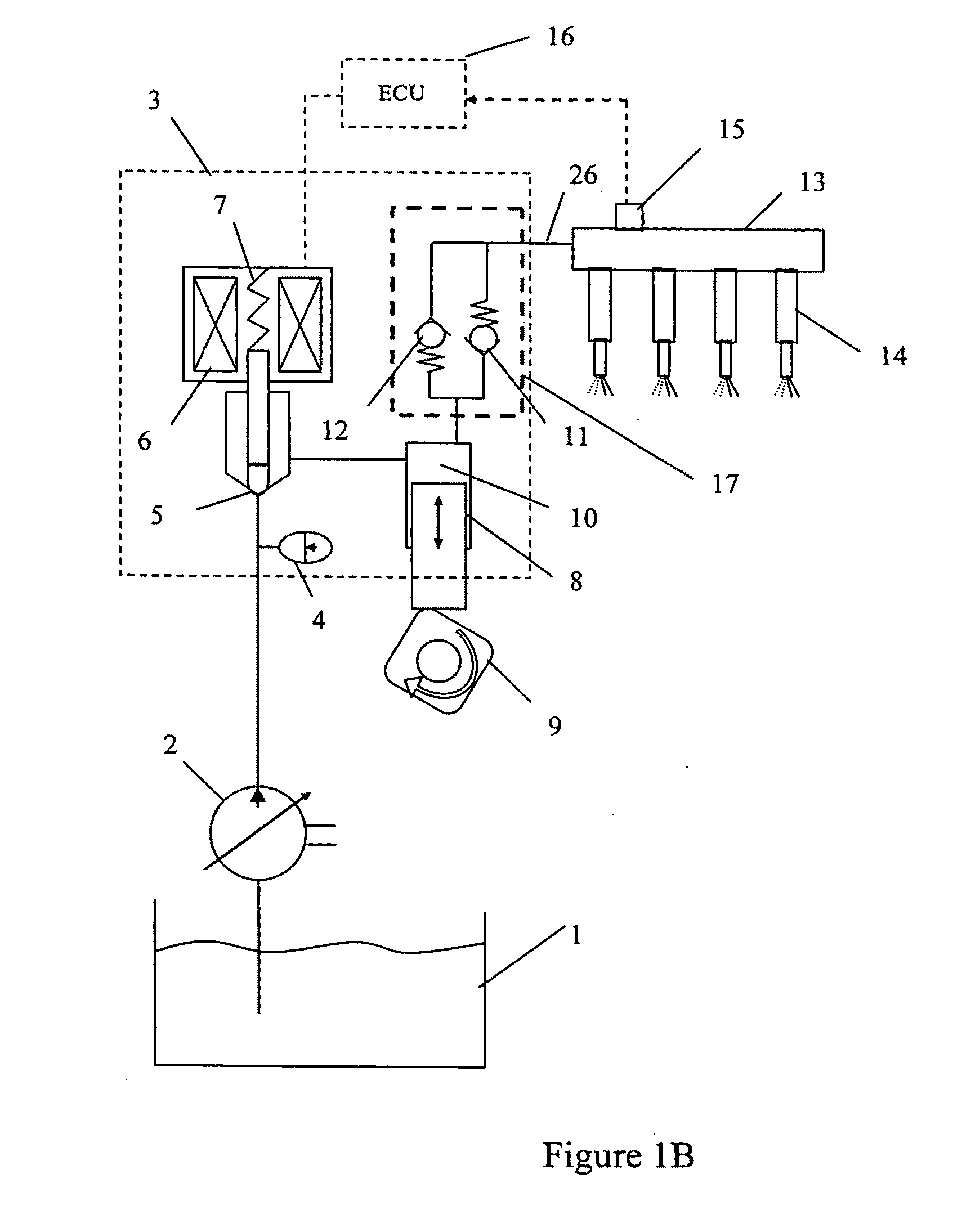
[0014]As represented in FIGS. 1A and 1B (collectively FIG. 1), a low-pressure pump 2 pressurizes fuel from the fuel tank 1, and delivers it to the high pressure pump housing 3 through an inlet fitting. The fuel passes under the influence of an accumulator 4 to a normally closed control valve 5. A normally open control valve is also applicable to such a fuel system. The fuel is drawn into the pumping chamber 10, where it is pressurized by the upward motion of the pumping piston 8 via the engine camshaft 9. The control valve 5 is acted upon by the control valve spring 7 and solenoid 6 to control the quantity of fuel delivered by the high pressure pump. This is accomplished by the accurate timing of the control valve closing relative to the pumping piston upward travel position. When the fuel is pressurized in pumping chamber 10, it travels through the outlet check valve 11, high pressure line 26, and into the common rail 13 that feeds the engine fuel injectors 14. Because the injector...


PUM


Abstract

A high pressure piston fuel pump having a discharge check valve between the pumping chamber and a pressurized fuel reservoir and a pressure relief valve between the fuel reservoir and a passageway in the housing, wherein the discharge check valve and the pressure relief valve are contained within a single fitting assembly affixed at the pump housing. A first end flow passage is in fluid communication with the pumping chamber and provides an inlet to the discharge check valve and an outlet from the pressure relief valve. A second end flow passage is in fluid communication with the fuel reservoir and provides an outlet for the discharge check valve and an inlet for the pressure relief valve. Advantages include the ability to pre-test the outlet check and pressure relief prior to assembly into the pump housing, and improved flexibility of the outlet fitting location.

Description

BACKGROUND[0001]The present invention relates to high pressure fuel supply pumps for gasoline common rail injection systems.[0002]Single piston, cam driven high pressure fuel pumps have become a common solution for generating high pressure fuel in common rail direct injection gasoline engines. It is known in the industry that the pump must incorporate an outlet check valve to prevent pressure bleed back from the rail while the pump is in the intake stroke cycle. It has become an industry requirement to incorporate a pressure relief valve within the pump to protect the entire high pressure system from an unexpected excess pressure caused by a system malfunction. In order to protect the rail and injectors, the pressure relief valve must be in hydraulic communication with the rail, i.e., in parallel with the pump flow. In order to make the parallel hydraulic communication, typical executions have located the outlet check valve and pressure relief valve as separate devices within the pu...

Claims


Application Information

Patent Timeline
IPC IPC(8): F02M69/46F04B7/00
CPCF02M59/366F02M59/462F02M59/485F04B53/10F02M63/0054F02M63/0265F04B49/22F02M63/005Y10T137/778Y10T137/7838Y10T137/7794
Inventor LUCAS, ROBERT G.DJORDJEVIC, ILIJA
Owner STANDYNE INC
Why Eureka
Try Eureka